1N4007 last purchased @ 2470 per box of 10 000, works out to about 3.2 cents each.
Friend used to make LED lights, that was his bulk price...MC Taiwan
You wants to fuss about parts of a cent...go ahead.
Friend used to make LED lights, that was his bulk price...MC Taiwan
You wants to fuss about parts of a cent...go ahead.
Turn the question inside-out and divide it into two pieces:
_
- Is it possible to design a circuit where the brand of 1N4007 DOES NOT MATTER AT ALL?
- Is it possible to design another circuit where the brand of 1N4007 is critical? The circuit works beautifully with one brand but fails miserably with another?
_
The OP was told to buy good quality diodes, from reputed suppliers, at the best price.
This automatically means the brand, factory, lot number and so on are not important, only that the supplied parts are of good quality.
Quality is defined as fitness for use.
The questions...I leave them to the more experienced members to answer.
This automatically means the brand, factory, lot number and so on are not important, only that the supplied parts are of good quality.
Quality is defined as fitness for use.
The questions...I leave them to the more experienced members to answer.
Chinese stuff is hit and miss.
I bought in 500 off 100nf caps.
One cap had one leg !
So they cant be checking every one for capacitance.
I bought in 500 off 100nf caps.
One cap had one leg !
So they cant be checking every one for capacitance.
Thanks for all of the replies. I'm just going to stick with known brands from reputable vendors and worry about something else.
IN4007s will vary in characteristics from vendor to vendor, especially regarding recovery time, as this is not a parameter specified on the data sheet. If you want to up your game a notch, you can buy the 1N4007GP from Vishay, which has a specified recovery time of 2 us, and will be less noisy as a consequence. UF4007s will be quieter still, as they have a shorter recovery time (75 ns) and a lower energy recovery spike/less recovered charge.
When I build switching power supplies for tube amplifiers, I like to use medium-fast recovery rectifiers like the FR306 (trr 500ns) for the input bridge rectifier. When using these diodes, at lot of conducted EMI down around 150kHz goes away. If you use std rectifiers and don't care about the vendor you can run into a situation where one vendor has decent EMI characteristics, while another will spray noise like a tom cat. The noise looks like a rising continuum down around 150 kHz, and probably rises at even lower frequency.
When I build switching power supplies for tube amplifiers, I like to use medium-fast recovery rectifiers like the FR306 (trr 500ns) for the input bridge rectifier. When using these diodes, at lot of conducted EMI down around 150kHz goes away. If you use std rectifiers and don't care about the vendor you can run into a situation where one vendor has decent EMI characteristics, while another will spray noise like a tom cat. The noise looks like a rising continuum down around 150 kHz, and probably rises at even lower frequency.
Last edited:
Are MDD (Microdiode Electronics) good? Their UF4007 are 1.54 cents each at qty 200 at Welcome to LCSC - LCSC.COM. Since local distributors tend to charge crazy 2000% markups on penny parts I sometimes look at lcsc.
LCSC is in Shenzhen, China...
Caveat Emptor.
Below the Indian bulk price for standard parts.
$0.0154 x 200 = $ 3.08.
Caveat Emptor.
Below the Indian bulk price for standard parts.
$0.0154 x 200 = $ 3.08.
We can't hear 150 kHz but this is a noise, and this noise worsens the whole device parameters (you'll see if you'll measure it)You can hear 150 kHz?
LCSC is in Shenzhen, China...
Caveat Emptor.
Below the Indian bulk price for standard parts.
$0.0154 x 200 = $ 3.08.
Unfortunately any low price component (diode, resistor, cap, TO-92 transistor) has a huge markup from distributors in the US. In the past I tried AliExpress and Ebay as a potential solution to that but almost everything was fake.
Buy in thousands (or at least hundreds) if you are worried about being price gouged on small quantity. When TO 92s and diodes get down to a nickel apiece I call it good enough. 25, 50 cents - eff that.
We can't hear 150 kHz but this is a noise, and this noise worsens the whole device parameters (you'll see if you'll measure it)
You often HEAR 120 Hz harmonics due to the switching noise. In the worst cases, every single burst of a couple hundred kHz can be heard as an individual ‘tick’ sound. String them together at a 120 Hz rate and you hear that quite clearly - sounds kind of like a bee. It’s never very loud, but a heck of a lot more noticeable than 120 Hz hum. Ever heard what it sounds like under 220kV high tension lines on a humid night? That’s it.
You risk getting off spec factory rejects to outright fakes at those prices.
And your volumes will not interest any factory representative to give you a price break.
And consider the landed cost at your doorstep, in order to compare the price.
It is going to cost something for the item to be packed and sent to you, count that in your per piece cost.
If you want to save $5 and spoil your project it is your decision.
Last edited:
Yes, and snubbers across secondaries clean it up. Since I started to put snubbers in my projects (and to devices under service/repair) I started to get much lower overall noise (both less regulated supply noise, and less output noise).You often HEAR 120 Hz harmonics due to the switching noise. In the worst cases, every single burst of a couple hundred kHz can be heard as an individual ‘tick’ sound. String them together at a 120 Hz rate and you hear that quite clearly - sounds kind of like a bee. It’s never very loud, but a heck of a lot more noticeable than 120 Hz hum. Ever heard what it sounds like under 220kV high tension lines on a humid night? That’s it.
Yes, and snubbers across secondaries clean it up. Since I started to put snubbers in my projects (and to devices under service/repair) I started to get much lower overall noise (both less regulated supply noise, and less output noise).
How would you adjust/improve the attached schematic with respect to snubbers? They came with red film caps for C1/2/4/5. They might be CBB, not sure. C3 is a yellow box safety cap.
I use a number of those supplies plus a variant with LM353 and another variant from diyaudio (denoiser/dienoiser).
Attachments
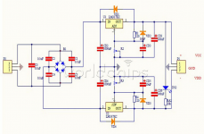
C3 must be a snubber but not a bare capacitor (RC but not C). C1/2/4/5 are helpful for high-frequency signal devices, e.g. AM-FM radio (usually don't help for audio frequencies). And if you use C1/2/4/5 then their capacitance has to be in the order of several nanofarads.How would you adjust/improve the attached schematic with respect to snubbers? They came with red film caps for C1/2/4/5. They might be CBB, not sure. C3 is a yellow box safety cap.
I would rather put two snubbers, each for every secondary, but not one for two secondaries in series. But one snubber is better than no snubber at all.
A typical snubber for your circuit is something like a 10-22 R resistor and 0.47-1.0 uF ceramic cap. I use film caps only with high voltages, >= 50..100 V.
Last edited:
- Home
- Design & Build
- Parts
- 1N4007 Rectifiers: Does Brand Matter?