I wouldn't go that high. Most folks use 20k for Rf1, as shown in the data sheet. A few months ago I was experimenting with LM3886 to drive electrostatic headphone transformers. After seeing this on page 23 of the LM3886 data sheet;
"The value for the feedback resistance, Rf1, should be chosen to be a relatively large value (10kΩ–100 kΩ), and the other feedback resistance, Ri, is calculated using standard op amp configuration gain equations."
I experimented (measurements and listening) with Rf1 values different than the standard 20k, keeping gain constant. I found the 'sweet spot' for Rf1 to be around 25k. Above and below that distortion increased.
For normal non-inverting use, I would definitely recommend balancing the impedances at the + and - inputs. In which case ouput DC offset will be minimal and you can remove C2.
I have found some op amp or amps become unstable with large feedback resistors.
The input capacitance along with Rf cause a phase shift which can cause oscillation.
The fix is a small capacitor across Rf.
The input capacitance along with Rf cause a phase shift which can cause oscillation.
The fix is a small capacitor across Rf.
I have found some op amp or amps become unstable with large feedback resistors.
The input capacitance along with Rf cause a phase shift which can cause oscillation.
Exactly.
The fix is a small capacitor across Rf.
An even better fix is to use a smaller feedback resistor.
Advantages of using a large feedback resistance:
- Lower current -> lower power dissipation in the feedback network.
- Lighter load on the amp, which can result in lower distortion.
Disadvantages of using a large feedback resistance:
- Higher noise, both thermal noise and also noise contribution from the amp's input current noise.
- Possible instability due to the input capacitance of the amp.
I'm not claiming this is a comprehensive list. These were just the advantages/disadvantages at the top of my mind.
In case of the LM3886, you'll want to stick to the 20-22 kΩ from the data sheet. You'll also want Cc, Cf, and Rf2 from "AC Test Circuit #2" of the data sheet. These components are necessary to deal with a little bit of parasitic oscillation that happens when the VAS in the LM3886 exits saturation (so as the LM3886 exits clipping).
Tom
Last edited:
GBWP of LM3886
Thank for all of your suggestion.
I have another question about GBWP.
From datasheet page 23 , Eq. 13 is a calculation of GBWP .
GBWP(eq13) = 1.3MHz --> the example is 100K and 8.2K
GBWP(22K,1K) = 2.3MHZ ---> my calculation AvxF3 = 23x100K = 2.3MHz
Specification of LM3886's GBWP = 2MHz(min)
From this 2 set of resistors(100K+8.2K and 22K+1K) , which one is a best ?
Last edited:
You'll also want Cc, Cf, and Rf2 from "AC Test Circuit #2" of the data sheet. These components are necessary to deal with a little bit of parasitic oscillation that happens when the VAS in the LM3886 exits saturation (so as the LM3886 exits clipping).
Tom, what test do you suggest to reveal this issue? I don't see any oscillations or overshoot in leading or trailing square wave edges without those parts, at high- or low-level.
GBWP? I'd like to buy a vowel.
From the datasheet, as specified in the question, P23 of link:
At this point, it is a good idea to ensure that the Gain-Bandwidth Product for the part will provide the designed
gain out to the upper 3 dB point of 100 kHz. This is why the minimum GBWP of the LM3886 is important.
GBWP ≥ AV × f3 dB = 13 × 100 kHz = 1.3 MHz
GBWP = 2.0 MHz (min) for the LM3886
Attachments
Last edited:
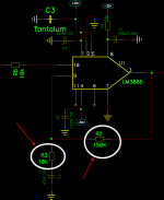
What happen or disadvantage if I put 150K and 10K for a gain setting resistor?..
Why would you want to do that? The chip can easily drive 20k. A 150k resistor is the same price as a 20k resistor. Yes, the low side capacitor can be a bit smaller at higher Z but this is the lowest-cost part of an amplifier. Power supply iron, caps, heatsinks, and box dominate the cost.
The gain-set network should be low-Z to control voltage noise (hiss).
The input devices of the chip have base current. And for good hiss and GBW, they flow high current. Read the spec. 1uA of bias current in a 20k resistor is already 20mV at the output. Of a chip with less than 10mV offset voltage with negligible resistances. Actually the trick is to make Rin and Rf1 nearly the same. Now the two bias currents cancel to about the input offset current, 0.2uA max (and typically much less). We can expect better than 4mV offset due to bias currents, comparable to the voltage offset. (So there is little benefit in going much below 20K either.)
Thank for all of your suggestion.
I have another question about GBWP.
From datasheet page 23 , Eq. 13 is a calculation of GBWP .
GBWP(eq13) = 1.3MHz --> the example is 100K and 8.2K
GBWP(22K,1K) = 2.3MHZ ---> my calculation AvxF3 = 23x100K = 2.3MHz
Specification of LM3886's GBWP = 2MHz(min)
From this 2 set of resistors(100K+8.2K and 22K+1K) , which one is a best ?
These are two different gain values, either ~12x or ~22x. So you can't directly compare it.
What is it you are worrying about with the resistor values?
Jan
Tom, what test do you suggest to reveal this issue?
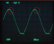
A simple sine wave test with 8 Ω load will do. Run the amp into clipping and you'll see a little buzz on the output as the amp exits clipping.
If you add Cc, Cf, and Rf2 you'll get a clean output all the way until the amp clips. Without them the buzz will degrade the amp's performance for the last ~5 W or so. That buzz is probably not overly friendly to tweeters either.
Tom
Attachments
These are two different gain values, either ~12x or ~22x. So you can't directly compare it.
What is it you are worrying about with the resistor values?
Jan
I try to follow a design guideline on page 23 (eq13)
So I confuse which one is better?
But you are the one that has to decide what gain you need. Then from the equation follow the resistor ratio.
The actual value for the resistors has been discussed above in terms of noise and stability.
Jan
The actual value for the resistors has been discussed above in terms of noise and stability.
Jan
- Home
- Amplifiers
- Chip Amps
- LM3886:Higher gain setting resistor value than usual.