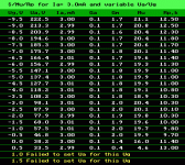
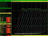
Did anyone try 6sn7(6n8) tubes at 3ma anode current supplied in the region of 200...400v ? I built sone output transformers that have the posibility to be wired for 13k load while not able to run at more than 13ma so i might need some 12sn7 tube run at 3...4ma.i can also wire them for 4 times that impedance, about 47k...
Attachments
Last edited:
Well, if you can run your OPTs at 13mA DC, why not run the tubes the same current, or closer to it, let's say 10mA?
You may have already considered this, but...
rp of a 6SN7/6N8S operated with 3mA Ia is going to be >10k ohms, so an OPT that presents a 13k load is not going to be optimal for that condition.
rp of a 6SN7 operated with 10mA Ia is going to be more like 7.5k, so while not optimal, should be better.
rp of a 6SN7/6N8S operated with 3mA Ia is going to be >10k ohms, so an OPT that presents a 13k load is not going to be optimal for that condition.
rp of a 6SN7 operated with 10mA Ia is going to be more like 7.5k, so while not optimal, should be better.
that's the max current for all the primaries in series...1/3rd of them can do 33ma, 2/3rd of them only 13ma...i won't run them hot as i have other options too.Well, if you can run your OPTs at 13mA DC, why not run the tubes the same current, or closer to it, let's say 10mA?
Not sure I got your point, but from the point of view of Idc, DC flux density increases linearly with the amount of turns. So if your maximum is 33mA DC at 1/3 of primary turns, then at 2/3 you should have 22mA and at 3/3 - 11mA.
1/3rd of the primary is made out of enammeled copper with a diameter of 0.15mm and 2/3rd of it is 0.09mm...I hope you understand it now.Not sure I got your point, but from the point of view of Idc, DC flux density increases linearly with the amount of turns. So if your maximum is 33mA DC at 1/3 of primary turns, then at 2/3 you should have 22mA and at 3/3 - 11mA.
Using a 6SN7 to drive a 47k Ohm load Resistor is one thing.
Easy Load!
Using a 6SN7 to drive most 47k Ohm output transformer primaries is a completely different thing:
47k Ohms at mid frequencies.
Low impedance at low frequencies (due to inductive reactance).
Low impedance at high frequencies (due to distributed capacitance).
Not an easy load.
Unless you only want mid frequencies, the others are rolled off, not Hi Fi.
Just my opinion.
Question:
What is your goal for the 6SN7 amplifier?
Watts out; output impedance; headphones; speakers; Line preamp; etc.?
Last edited:
1/3rd of the primary is made out of enammeled copper with a diameter of 0.15mm and 2/3rd of it is 0.09mm...I hope you understand it now.
There are multiple possibilities, but without clarification from your part, there's no need to continue further,
6A3sSummer, what's the problem designing a 200H primary inductance and 200pF shunt capacitance transformer specially for a 6N8S and similar? Especially 1:1 transformers are a piece of cake, however even step-down line-output transformers are possible.
As I understand it, the figure of merit for low frequency response from the OPT is going to be primary inductance (Lpri).
If rp of the 6SN7 is 10k ohms, the Lpri will need to be a hefty 150 Henries to get F3 of 10.6Hz.
If you want ruler flat down to 50Hz, that would mean F3 at about 5Hz, which would mean Lpri of about 300H.
That's a pretty tall order.
What's the primary inductance of this OPT?
--
If rp of the 6SN7 is 10k ohms, the Lpri will need to be a hefty 150 Henries to get F3 of 10.6Hz.
If you want ruler flat down to 50Hz, that would mean F3 at about 5Hz, which would mean Lpri of about 300H.
That's a pretty tall order.
What's the primary inductance of this OPT?
--
50AE,
I said MOST 47k transformers.
The plate impedance, rp, of a 6SN7 that has only 3 or 4 mA, is about 10k Ohms (as was stated at least 2 times in posts in this thread).
200pF capacitive reactance at 20kHz is only 39.8k Ohms.
For a 47k load, and 39.8k capacitive reactance, the frequency response is just over -3dB at 20kHz.
That means it is -1 dB down at 10kHz.
Hi Fi?
Just my opinions.
And, as I often say . . .
"All Generalizations Have Exceptions"
Last edited:
headphonesQuestion:
What is your goal for the 6SN7 amplifier?
Watts out; output impedance; headphones; speakers; Line preamp; etc.?
50AE,
I said MOST 47k transformers.
My bad, sorry!
The plate impedance, rp, of a 6SN7 that has only 3 or 4 mA, is about 10k Ohms (as was stated at least 2 times in posts in this thread).
200pF capacitive reactance at 20kHz is only 39.8k Ohms.
For a 47k load, and 39.8k capacitive reactance, the frequency response is just over -3dB at 20kHz.
That means it is -1 dB down at 10kHz.
Hi Fi?
There's something wrong within your math.
A 10k impedance driving a 200pF shunt capacitance translates to a -3dB cutoff point of 79.6kHz
Inductance wise, for 200H it gives a -3dB cutoff at 8Hz.
If loaded with 47k, frequency becomes 6.6Hz - 97kHz
Last edited:
50AE,
You are correct, there is something wrong with my math.
But, now that you have made me look closer, let's get it completely right this time . . .
6SN7 u = 17 - 20, let's use 20.
Gain is u x (ZL/(ZL + 10k rp))
Gain is 20 x (ZL/(ZL + 10k rp))
Gain at 1kHz is 20 (47k/57k) = 16.5
The gain at 20kHz is less than that, because of the lower load impedance (complex impedance of 47k in parallel with 39.8k).
1. The resistive impedance of 47k at 1 kHz is driven by 10k
2. The complex impedance: 39.8k Xc in parallel with 47k resistance, is also driven by 10k.
I will let you do the trigonometry to figure the complex impedance at 20kHz.
Thank You!
. . . That is because it is very late here, and I will have to bone up on my trig functions, sorry.
Without thinking harder, I know the complex impedance at 20kHz will be less than 1.414 x (47k/2); it will be less than 33.2k Ohms.
I believe you will see that we are not going to have 97kHz bandwidth.
Right?
Last edited:
Ok, being a math lazy person, I LTspiced this with a 6SN7 model, with an anode voltage of 100V, -3Vbias and 3mA anode current with a 1k resistor. The stage gain is 20.5. The plate impedance according to LTspice is 10.7k.
The resulting frequency response with an unloaded 200pF interstage goes to 70kHz at -3dB.
With a secondary loaded with 47k, it extends to 85.6kHz
As a temporary shallow conclusion, there is deviation from a small ideal voltage generator with series resistance, probably due to the tube's dynamic resistance, but it's small compared to your numbers.
Remember reactance is not the same as pure resistance.
50AE,
I give up. You are absolutely right.
Just answer one question, please?
What simulator shows a triode stage gain, Av, that is larger than u?
Thanks!
I give up. You are absolutely right.
Just answer one question, please?
What simulator shows a triode stage gain, Av, that is larger than u?
Thanks!
Last edited:
50AE,
Let me answer my own question from Post # 19
You said:
Plate Load RL = 47k
Plate impedance rp = 10.7k
Stage Gain = 20.5
Let us leave the 200pF cap out of the circuit (normally, a cap does not have gain, but who knows?).
Stage Gain = u x (RL/(RL + rp))
20.5 = u x (47k/(47k + 10.7k)
20.5 = u x (47k/57.7k)
20.5 = u x (0.8146) in round numbers
20.5/0.8146 = u
u = 25.165 in round numbers
Problem solved, your simulation program uses a 6SN7 that has a u = 25.165
But . . . What manufacturer makes a triode with a u = 25.165, and calls the tube a 6SN7?
Is this a problem with the tube manufacturer, the tube spice model, or the simulation program?
Thanks!
Last edited:
- Home
- Amplifiers
- Tubes / Valves
- 6(12)SN7-6n8 at 3...4ma anode current


