
Your power is limited by the current sink (about 1.25A) and the supply.
The SL6 is not an easy load (I used to own a pair) and so if we assume a max voltage swing from the -/+12 volt rails of around -/+ 9.5 volts that gives us around 6.7 volts rms into an easy resistive load.
I would guess realistically around 4 to 6 watts rms into the SL6. The level might be even lower at high frequency.
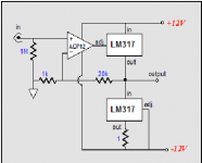
the lower regulator limits at -9.3V, the upper one at +10.6V, it would make sense to lower the neg supply by 1.25V. The offset will be quite high(+/-20mV) and the cooling will require huge sinks and the KTT version
Thanks for your explanation Sir,
So, what s the simple diy amp that can drive SL6 Speaker ?
Well your limit here is the very low supply voltage. The SL6 is only 82db/1watt meaning it is very insensitive.
Have a look at post #20 here which deals with the SL100 (I still have those). The SL6 is even worse for efficiency.
How much headroom is needed
So before you can decide what amp to build you need to determine what power you want. If you don't play it loud then a few watts might be enough.
You can find some answers and ideas in these threads:
SE class A regulator-chip-amp madness
The Voltage-Regulator-Chip Amp family welcomes a new member:
Yet another funny Chip-Amp
And now, the Regulator-Chip JLH Amp.
What happens when you cross a Tringlotron with a Regulator-Chip Amplifier?
Class A Chip Amp: and now, the complementary version
Just for fun: The Regulator-Chip amplifier
I have try The TEA2025 Bridge to drive SL6, but the sound is broken,
How if those 2 LM317 supplied with +/- 24 volt?
is there any chance about ten watt could drive SL6 ?
Thanks so much for your enlightment ;-)
How if those 2 LM317 supplied with +/- 24 volt?
is there any chance about ten watt could drive SL6 ?
Thanks so much for your enlightment ;-)
You need something much better than a TEA2025 and 24 volts is probably getting a bit high for the LM317. The problem with the LM317 is its limited current ability.
An LM3886 chip amp would be good and with it running on around -/+ 25 volts.
An LM1875 is very easy to use and would be OK (decent levels) running on -/+25 volts. Lots of kits for all these.
Both these would also run very cool when idling.
An LM3886 chip amp would be good and with it running on around -/+ 25 volts.
An LM1875 is very easy to use and would be OK (decent levels) running on -/+25 volts. Lots of kits for all these.
Both these would also run very cool when idling.

Your follower and the 317 circuit you showed initially operate in class A, which severely limits the output power and causes a huge dissipation: your MoFo will dissipate around 100W, with is difficult to manage.
Some of the 317 circuit examples I proposed operate in class B or in an improved, channel-correlated class A for a reduced dissipation and higher output.
In class B, as a 317 can deliver ~1.7A peak when properly cooled, you could theoretically arrive at 12W sine power; more realistically 10W.
But the best solution is to opt for a dedicated chipamp: this section contains many usable examples, based on good, commonly available ICs
I think you need to draw up your own specification for what you want 🙂 Things such as whether you want Class A (hot hot hot), how much power you really want, and having decided that you can then look at what sort of power supply and heatsinks you need.
The follower has a voltage gain of slightly less than 1 so you need a preamp stage. It also has a massive power dissipation of about 160 watts for a two channel stereo set up. Massive heatsinks, massive power supply... that's not my thing at all 😉
So think what you really want first.
The follower has a voltage gain of slightly less than 1 so you need a preamp stage. It also has a massive power dissipation of about 160 watts for a two channel stereo set up. Massive heatsinks, massive power supply... that's not my thing at all 😉
So think what you really want first.
(I bet you know this but for general entertainment🙂
Worse: good class A (choke-load or push-pull) approaches 50% efficient; this constant current scheme is 25% efficient at best.
In other words, you need twice as much stuff to get a specified output. Transformer. Heatsink.
I've seen it for a headphone amp. (SWTP) And thought it wasteful. Never seen it seriously proposed by an able designer for loudspeaker duty (I'm sure it has been done).
Your follower and the 317 circuit you showed initially operate in class A, which severely limits the output power...
Worse: good class A (choke-load or push-pull) approaches 50% efficient; this constant current scheme is 25% efficient at best.
In other words, you need twice as much stuff to get a specified output. Transformer. Heatsink.
I've seen it for a headphone amp. (SWTP) And thought it wasteful. Never seen it seriously proposed by an able designer for loudspeaker duty (I'm sure it has been done).
- Home
- Amplifiers
- Chip Amps
- Plan to make LM 317 power amp