Hey fellas, I'm havin a bit of trouble with a Rotel RB-2000 a friend brought to me to see if I could tune up for him.
It was going into protect, but both sides were showing minimal DC output, and adjusted down to single digits. Protection issue was resolved with some new electrolytic caps on the protection board. Great, now it powers on and stays on. One side adjusted up per the service manual just fine. I adjusted the dc and the bias, and tested it, and it works fine.
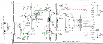
The other channel, dc offset seemed to adjust fine. But bias was showing 0.0v no matter what. I put a sine wave signal to it, and regardless where I probe, the wave form appears fuzzy on the positive side. Probing around with a voltmeter, I found voltages that match the schematic below in all green marked locations. There is clearly a problem in the bias section of the circuit, the varistor or so it is called by rotel shows a 3 diode drop, so within spec, but the voltages are high on the negative side between q109 and q110.
I'm thinkin there must be a problem with q109 or q110. None of the transistors on the amplifier test bad with a multimeter in diode mode.
Lookin for ideas on what to test next, and how to do it. Of course, old transistors, 2sa914, 2sa913, 2sc1913 are no longer available. Recommendations on modern replacements? Will ksc3503 and ksa1381 work as replacements for those? also am I remembering wrong, but isn't it getting tough to find these in matching gain ratings? Or since these are VAS does it not matter as much?
Here is a schematic with my voltage checks. Thanks for the advice.
It was going into protect, but both sides were showing minimal DC output, and adjusted down to single digits. Protection issue was resolved with some new electrolytic caps on the protection board. Great, now it powers on and stays on. One side adjusted up per the service manual just fine. I adjusted the dc and the bias, and tested it, and it works fine.
The other channel, dc offset seemed to adjust fine. But bias was showing 0.0v no matter what. I put a sine wave signal to it, and regardless where I probe, the wave form appears fuzzy on the positive side. Probing around with a voltmeter, I found voltages that match the schematic below in all green marked locations. There is clearly a problem in the bias section of the circuit, the varistor or so it is called by rotel shows a 3 diode drop, so within spec, but the voltages are high on the negative side between q109 and q110.
I'm thinkin there must be a problem with q109 or q110. None of the transistors on the amplifier test bad with a multimeter in diode mode.
Lookin for ideas on what to test next, and how to do it. Of course, old transistors, 2sa914, 2sa913, 2sc1913 are no longer available. Recommendations on modern replacements? Will ksc3503 and ksa1381 work as replacements for those? also am I remembering wrong, but isn't it getting tough to find these in matching gain ratings? Or since these are VAS does it not matter as much?
Here is a schematic with my voltage checks. Thanks for the advice.
Attachments
Last edited:
just curiosity
will Q111 C E voltages change when you trim VR102, (-5.4v, 7.5v),
will Q111 C E voltages change when you trim VR101,
voltage on Q110 E?
if unsolder and lift up one leg of R126 and R127, what is the voltage on pin16,
( this will turn off all the power transistors )( will there be voltage across R123, R122? )
would there be bad solder joints.
Hi Alex,
I'll check that stuff out tonight and post back. Thanks.
I did check for bad solder joints, pretty much my first task when I start troubleshooting old stuff. So common, but none on this one yet...
I'll check that stuff out tonight and post back. Thanks.
I did check for bad solder joints, pretty much my first task when I start troubleshooting old stuff. So common, but none on this one yet...
just curiosity
will Q111 C E voltages change when you trim VR102, (-5.4v, 7.5v),
will Q111 C E voltages change when you trim VR101,
voltage on Q110 E?
if unsolder and lift up one leg of R126 and R127, what is the voltage on pin16,
( this will turn off all the power transistors )( will there be voltage across R123, R122? )
would there be bad solder joints.
Hi Alex. Adjusting vr101 does change the voltages around q111, but won't rise above -3.9v and -5.8v.
Q110 E reads -64.1v.
I didn't lift the resistors to remove the output devices from the circuit yet. Hopefully tomorrow.
Thanks for your help.
Is there any of that black glue on any of the boards?
Or any type of glue visible?
The modern/recent Rotel's used this glue to hold stuff in place, and over time it becomes conductive, causing all sorts of crap.
Or any type of glue visible?
The modern/recent Rotel's used this glue to hold stuff in place, and over time it becomes conductive, causing all sorts of crap.
None. I hate that stuff and actively remove the glue and replace parts damaged by it when I come across it. This appears to be pre glue. There are 0 electrolytic caps on the board, and I usually see that stuff holding down electrolulytic caps. I have not gone through the power supply board so there may be some there, but haven't spotted it. it uses a smaller power supply board for power supply on the front end, but both amp boards Measure the same power supy voltages.
I am curious if the voltages on Q111 C E could be adjusted to around 2.7v by VR102.
take precaution to measure it.
take precaution to measure it.
I am curious if the voltages on Q111 C E could be adjusted to around 2.7v by VR102.
take precaution to measure it.
Hi Alex, I was away on vacation for a while, and now that I am home, I finally made it back to this. I measured the voltage drop across Q111 C E, and i was able to adjust it to 2.7V with VR102.
Q111 C E can be adjusted to 2.7v so Q111 is ok.
measure Q111 C E again,
this time place the black probe of the DMM at point 16 of the board,
use red probe of the DMM to measure the voltage of Q111 C E,
it should be around +1.35v at Q111 C, and -1.35v at Q111 E.
re-solder Q112 and Q113, R122, R123, R124, R125, R126, R127 and the surrounding.
check the values of the above resistors.
- Home
- Amplifiers
- Solid State
- Rotel RB-2000 troubles