I also used Audacity, but that is not the whole story.
I upsampled to 192/24 and saved the file.
Then I reloaded the 192/24 file to check wether is was indeed 192/24.
The reason I mention this is because Audacity is a bit tricky and may store a file in a different way as was instructed.
After having reloaded the the 192/24 I resampled it to 44.1 and reduced the bitdepth to 16bit including dither.
So to compare various opinions it may be better to use the 6 files that I made.
Hans
Hans, I just read online (I don't know whether it's correct) that Audacity's sample rate converter (SRC) features two selectable utilities. One is SoX, which apparently is a floating-point SRC, while the other is a fixed-point SRC of which I'm not familiar. Can you confirm whether your resampled files were produced in floating-point (SoX), or fixed-point (the other SRC)? This, of course, will determine what kind of FIR interpolation-filter was utilized by Audacity in the rate conversion processing.
Last edited:
Thanks Hans, it was a nice joint action.
Just again, for the readers, did this prove anything ? Was there a thesis on the Test ?
Doede, if I'm correctly reading Hans's chart, his experiment showed that the digital interpolation-filter which was utilized by Audacity in the sample rate conversion process, is not subjectively transparent. What we hope to discover with the upcoming PGGB based experiment is an subjectively transparent conversion.
well described ken 😎 thx
btw I also experienced similar with the up and down sampling within Roon...
The only thing you cannot do with Roon, is Upsample and then downsample again. Nevertheless, sound impact was similar with that "test"
btw I also experienced similar with the up and down sampling within Roon...
The only thing you cannot do with Roon, is Upsample and then downsample again. Nevertheless, sound impact was similar with that "test"
Last edited:
Hans, I just read online (I don't know whether it's correct) that Audacity's sample rate converter (SRC) features two selectable utilities. One is SoX, which apparently is a floating-point SRC, while the other is a fixed-point SRC of which I'm not familiar. Can you confirm whether your resampled files were produced in floating-point (SoX), or fixed-point (the other SRC)? This, of course, will determine what kind of FIR interpolation-filter was utilized by Audacity in the rate conversion processing.
Ken,
Audacity has four selectable sample rate converters:
1) Low quality (fastest)
2) Medium quality
3) High quality
4) Best quality (slowest)
From these 4 options I have chosen #4, best quality, but I have no idea of the technical details behind this conversion.
Hans
To get back to the discussion about transimpedance amplifiers: Hans, I saw here https://www.diyaudio.com/forums/digital-line-level/373375-discrete-converter-16.html#post6700861 that you have confirmed that the transition time of your DAC is 2 ns or less. What kind of voltages do you get at the DAC output and at the op-amp virtual ground when you simulate the straightforward and MFB version with such transition times?
Marcel,
Will simulate this tomorrow, the just recorded Dac waveform as input to the MFB variant and also the original virtual gnd input version, both with the LT1468 and with the OPA1611 that TI advises.
Can compare this to my recordings at the output of the LT1468 to check how reliable the spice model is.
Hans
I did not simulate, but I measured first before doing a sim at a later stage.
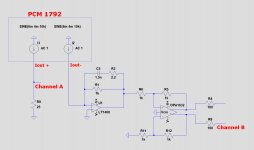
Measuring is more revealing, for which I used the circuit in the first image below.
Both channels from the Dac where used, Iout+ going to 50R//50R termination, and Iout- to the original circuit with LT1468.
The 2.2R in series with the 1.5nF used to be 10R and the only reason I could think of why Bel Canto inserted this was for stability reasons.
I lowered this to 2.2R and noticed no stability issues.
A few things that I noticed:
1) The AC output signal on the 25R side did not change a bit in shape or magnitude with or without compensating for the 6mA bias current.
2) Idem when connecting the other side Iout- to the LT1468.
3) I used the the output from the OPA1632 with the same polarity as the signal on the 25R. but since it's second input is tied to gnd, gain is 0.5
Difference in LF gain between the two signals is now 1K*0.5/25R = 20
4) the 100R behind the OPA1632 in series with the scope's 8pF input has a BW of 200Mhz, so that won't influence the measurement.
5) when using both scope channels, the horizontal sample interval doubles to 4nsec.
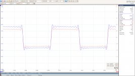
The second image shows the output to the scope's Channel A and Channel B for a 1Khz -12dBFs square wave, with both channels LF filtered @ 100Khz, proving the functioning as expected and with a gain of 20.
Thid image shows the same somewhat magnified in time, but now unfiltered.
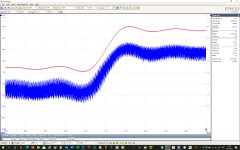
Fourth image is magnified from a point in time on the upgoing slope, horizontally 200nsec/div and vertically both channels the same 20mV/div.
It is a bit hard to see, but the 200mV upwards slope in red, translates into 10mV over the 25R resistor in blue.
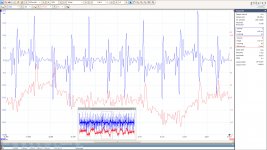
Fifth image shows the two output signals for a zero signal offered to the Dac , giving more resolution in the vertical axis of resp. 5mV/div for the 25R output side and 2mV/div for the LT1468 side as shown on a 100nsec/sec scale
The large almost +/-1mA nsec peaks on the 25R are hardly visible in the output of the I-V converter side.
But closer inspection of the signals between the large peaks each with a distance of 82nsec, shows a pattern that when the Dac takes one step down in this 82nsec period, that the I-V converter follows with a 200nsec halve sine wave downwards, and the same for one step upwards from the Dac.
Notice that this is the signal from the OPA1632 output, the signal on the LT1486 is twice as large, so still very small.
The step size on the 25R is ca. 2.5mV, translating in a 100uA resolution.
So my first impression is that the LT1468's input does not get overloaded by the 2nsec 1mA transients because it reacts almost immediately on a single 82nsec up and down step.
Hans
.
Measuring is more revealing, for which I used the circuit in the first image below.
Both channels from the Dac where used, Iout+ going to 50R//50R termination, and Iout- to the original circuit with LT1468.
The 2.2R in series with the 1.5nF used to be 10R and the only reason I could think of why Bel Canto inserted this was for stability reasons.
I lowered this to 2.2R and noticed no stability issues.
A few things that I noticed:
1) The AC output signal on the 25R side did not change a bit in shape or magnitude with or without compensating for the 6mA bias current.
2) Idem when connecting the other side Iout- to the LT1468.
3) I used the the output from the OPA1632 with the same polarity as the signal on the 25R. but since it's second input is tied to gnd, gain is 0.5
Difference in LF gain between the two signals is now 1K*0.5/25R = 20
4) the 100R behind the OPA1632 in series with the scope's 8pF input has a BW of 200Mhz, so that won't influence the measurement.
5) when using both scope channels, the horizontal sample interval doubles to 4nsec.
The second image shows the output to the scope's Channel A and Channel B for a 1Khz -12dBFs square wave, with both channels LF filtered @ 100Khz, proving the functioning as expected and with a gain of 20.
Thid image shows the same somewhat magnified in time, but now unfiltered.
Fourth image is magnified from a point in time on the upgoing slope, horizontally 200nsec/div and vertically both channels the same 20mV/div.
It is a bit hard to see, but the 200mV upwards slope in red, translates into 10mV over the 25R resistor in blue.
Fifth image shows the two output signals for a zero signal offered to the Dac , giving more resolution in the vertical axis of resp. 5mV/div for the 25R output side and 2mV/div for the LT1468 side as shown on a 100nsec/sec scale
The large almost +/-1mA nsec peaks on the 25R are hardly visible in the output of the I-V converter side.
But closer inspection of the signals between the large peaks each with a distance of 82nsec, shows a pattern that when the Dac takes one step down in this 82nsec period, that the I-V converter follows with a 200nsec halve sine wave downwards, and the same for one step upwards from the Dac.
Notice that this is the signal from the OPA1632 output, the signal on the LT1486 is twice as large, so still very small.
The step size on the 25R is ca. 2.5mV, translating in a 100uA resolution.
So my first impression is that the LT1468's input does not get overloaded by the 2nsec 1mA transients because it reacts almost immediately on a single 82nsec up and down step.
Hans
.
Attachments

And now for the sim.
When offering the same 1mA transient followed by a 100uA current over a 82nsec period in blue, I get LTSpice's output in red for the circuit as used in the previous posting.
This may prove that for this kind of events, opamps are not modelled accurate enough.
Hans
.
When offering the same 1mA transient followed by a 100uA current over a 82nsec period in blue, I get LTSpice's output in red for the circuit as used in the previous posting.
This may prove that for this kind of events, opamps are not modelled accurate enough.
Hans
.
Attachments

What does the voltage at the negative input of the LT1468 look like? It has a bipolar differential pair input, so a voltage greater than 52 mV will drive it into slew rate limiting, and any voltage that's not much smaller than 52 mV will drive it into slewing induced distortion.
When simming the shown current input signal, I see a 30mV peak at the input.
I will probably be hard to get any better information.
Hans
I will probably be hard to get any better information.
Hans
Does the hypothesis of post #673 still make sense with sub-2 ns transitions or is it now a mystery why the DAC with MFB transimpedance amplifier intermodulates more strongly?
Ken,
Hans
Hans, did you see and successfully download the PGGB files?
Does the hypothesis of post #673 still make sense with sub-2 ns transitions or is it now a mystery why the DAC with MFB transimpedance amplifier intermodulates more strongly?
I have already taken the MFB stuff apart, so I can’t do another measurement on this topology, but I disliked the sound.
The only thing measured that gave something of a clue away was that the HF noise was very much larger as with the original voltage feedback amp.
But those simulations in #573 cannot be trusted in any way as shown a few postings back.
Hans
Hans, did you see and successfully download the PGGB files?
Yes Ken, I have seen them and have read all the added comment.
Great it went so fast
Will try to distribute the files tonight.
Hans
Yes Ken, I have seen them and have read all the added comment.
Great it went so fast
Will try to distribute the files tonight.
Hans

And now for the sim.
When offering the same 1mA transient followed by a 100uA current over a 82nsec period in blue, I get LTSpice's output in red for the circuit as used in the previous posting.
This may prove that for this kind of events, opamps are not modelled accurate enough.
Hans
.
I wouldn't trust the models. Notwithstanding that the models could be correct for the NE5532/4 the feedback capacitor is critical to performance. The internal capacitive compensation (at a lower frequency than many high speed devices) creates a common base shorted output stage at high frequencies. The feedback capacitor connected to this output shorts the input transients to the output and back into the internal compensated common base at high frequencies. Hence transients are not going forward through the input rather going backward into the output as thereupon drastically minimizing input overload.
This is why a device that looks like it has nothing going for it has operated as a classic I/V converter for decades.
I hope I've done everything right.
Here are four 44.1/16 .wav files in original format and four up-sampled by PGGB to 88.2/32 and back to 44.1/16.
Dropbox - NOS-44.1 - Simplify your life
I will still convert 88.2/32 to 88.2/24 so everybody can use them.
Please PM your findings to me personally to prevent influencing each other.
After having received at least 5 reactions I will disclose.
Hans
PGGB resampled test files ready
This post is to highlight Hans' post #777 above. It contains a Dropbox link to the PGGB resampled song files. Hans has made our digital filter experiment easy for everyone to conduct with his prepared test files, so please participate. This should be interesting. 🙂
This post is to highlight Hans' post #777 above. It contains a Dropbox link to the PGGB resampled song files. Hans has made our digital filter experiment easy for everyone to conduct with his prepared test files, so please participate. This should be interesting. 🙂
Last edited:

- Home
- Source & Line
- Digital Line Level
- What do you think makes NOS sound different?