Seems Im going through a 100 watt phase.
Really enjoy simple to some what complicated designs in the 100 watt @4ohm
power level. Or basically class AB with 35 to 38 volt rails
Also really enjoy lately the performance in simulation
of Fairchild 2SA1381 / 2SC3503 Transistors
Sold as KSA1381TSU and KSC3503DSTU
manufactured by On Semi through the usual distributors
This whole design started as a comical joke to myself.
Since these transistors seem to have good linearity
and high fT around 150 MHz.
I thought to myself ...
what if I just made a whole amplifier with just these transistors.
Would almost seem odd making a
Input stage, Vas and driver stage all with the same transistor.
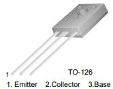
Also since its a TO-126 package

Well it actually started not sounding too crazy
since I like using current mirrors and current mirrors as current sources.
Ideal with board design it would be nice to thermally bond
the current sources, current mirrors and differential stage transistors.
So with a T0-126 package it would be rather easy
to mount them back to back.
And could be held together easily for what would seem
a pretty easy way of thermally bonding a transistor pair.
So be it. I decided to put together a Model in Tina TI
and see what a hysterical failure a all T0-126 amplifier could be.
Aside of course output devices be typical 247 or 264 packages for high current.
Im using MJL3281 / 1302 T0-264 packages for output devices
So I put together a basic design, which actually went rather well.
And with pretty standard capacitor values and minimal resistor count.
Got a sinewave to appear 🙄 LOL.
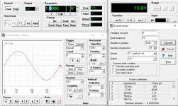
So I tapped the Fourier Analysis function in Tina TI
and it seems as if my Comical Idea is not much of a joke.
With 1 volt RMS input for full clean power at 8 ohms.
1 kHz harmonic distortion seemed to be .005 % 🙂

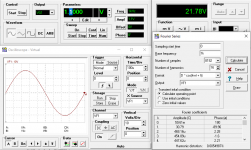
If I lower the compensation capacitor values a little bit, and remove stability network
on the output I can get it down to .002 % @ 1kHz
But in real life I will likely stick to higher values for stability.
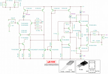
Using values shown in posted schematic/ screen shot of the TINA TI model
with the usual output stability networks

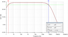
Frequency response seemed pretty good
Gain is set to around 29 dB so -3 dB response is around
1.8 Hz to 771 kHz

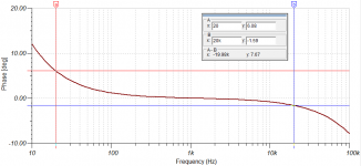
Phase in audio band around 6 deg @ 20 Hz and -1.59 deg @ 20 kHz

Really enjoy simple to some what complicated designs in the 100 watt @4ohm
power level. Or basically class AB with 35 to 38 volt rails
Also really enjoy lately the performance in simulation
of Fairchild 2SA1381 / 2SC3503 Transistors
Sold as KSA1381TSU and KSC3503DSTU
manufactured by On Semi through the usual distributors
This whole design started as a comical joke to myself.
Since these transistors seem to have good linearity
and high fT around 150 MHz.
I thought to myself ...
what if I just made a whole amplifier with just these transistors.
Would almost seem odd making a
Input stage, Vas and driver stage all with the same transistor.
Also since its a TO-126 package
Well it actually started not sounding too crazy
since I like using current mirrors and current mirrors as current sources.
Ideal with board design it would be nice to thermally bond
the current sources, current mirrors and differential stage transistors.
So with a T0-126 package it would be rather easy
to mount them back to back.
And could be held together easily for what would seem
a pretty easy way of thermally bonding a transistor pair.
So be it. I decided to put together a Model in Tina TI
and see what a hysterical failure a all T0-126 amplifier could be.
Aside of course output devices be typical 247 or 264 packages for high current.
Im using MJL3281 / 1302 T0-264 packages for output devices
So I put together a basic design, which actually went rather well.
And with pretty standard capacitor values and minimal resistor count.
Got a sinewave to appear 🙄 LOL.
So I tapped the Fourier Analysis function in Tina TI
and it seems as if my Comical Idea is not much of a joke.
With 1 volt RMS input for full clean power at 8 ohms.
1 kHz harmonic distortion seemed to be .005 % 🙂
If I lower the compensation capacitor values a little bit, and remove stability network
on the output I can get it down to .002 % @ 1kHz
But in real life I will likely stick to higher values for stability.
Using values shown in posted schematic/ screen shot of the TINA TI model
with the usual output stability networks
Frequency response seemed pretty good
Gain is set to around 29 dB so -3 dB response is around
1.8 Hz to 771 kHz
Phase in audio band around 6 deg @ 20 Hz and -1.59 deg @ 20 kHz
Attachments

Last edited:
What fixes the current in the current mirrors - you seem to have only mirrors, so what's to stop the current varying spontaneously - R5 will limit the maximum value, but what stops the current falling to zero?
It seems you may not ever have seen the Gerry Sussman (MIT professor of EECS / AI) lecture about early 1970s AI programs, trying to figure out the uA741 opamp by "reasoning" rather than circuit simulation. Eventually, after dozens of CPU hours (on PDP-10 machines @ 300 kilo instructions per second) the AI stumbled upon grasped the solution. There's one resistor that determines ALL of the bias currents.
_
_
Attachments

The only issue with that is that the bias current is power supply voltage dependent. If the “resistor” were replaced by a constant current (ie, add a 3rd transistor to the one of the mirrors, and make it a true CCS) that issue is eliminated. Or use a CCS in place of the resistor. Ripple and supply bounce can cause IM distortion that doesn’t show up in a simulation, unless the entire power supply is modeled. Regulated supplies used with op amps tend to prevent this. It is also good practice to add a few ohms or lens of ohms of emitter degeneration to the mirrors if using discretes. Not necessary in an IC.
The only other issue is whether one single driver transistor is up to the task. Those types are a little small - I might parallel two. Certainly would if using a supply over about +/-35 or 40 volts. Add a hundred ohms of base stopper in each to ensure current sharing.
The only other issue is whether one single driver transistor is up to the task. Those types are a little small - I might parallel two. Certainly would if using a supply over about +/-35 or 40 volts. Add a hundred ohms of base stopper in each to ensure current sharing.
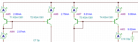
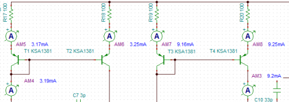
Kinda nerve racking that the PNP "current mirror" consisting of T3 and T4, has such unequal currents in the two legs. 7 mA in T3 [(35+35-1.4)/10K] and 9mA in T4 if the purple text on simulated ammeter AM3 is correct. Possibly a second good reason to add emitter degeneration in all mirrors. Choose R such that (I*R) > 350 mV.
The only issue with that is that the bias current is power supply voltage dependent....
See R4 on this '741 scheme. It sets a Vbe equal to a Vbe+R.
https://rodanski.net/ben/work/symbolic/ua741/ua741.gif
The current varies very much less than the voltage. Historically we used '741 down to 9V in low-expectation applications, and they served well. We see that the current may double from 5V to 40V (past ratings but what the heck) and a doubling of current is usually a not-large change of performance.
The 10r in the Dragon's plan may not stabilize the current so much. However his amplifier may get less oddball supplies than the '741 is historically expected to suffer.
Attachments
Last edited:
Yes in the business that's called a Widlar Current Sink and its mathematical analysis does not reduce to a closed form expression: Ya Gotta Iterate. Which they did, in 1967, with their slide rules. The same slide rules that Lockheed used in 1961, to design the fastest runway launched airplane that ever flew. 2100 MPH, Mach 3.3, SR-71.
Kinda nerve racking that the PNP "current mirror" consisting of T3 and T4, has such unequal currents in the two legs. 7 mA in T3 [(35+35-1.4)/10K] and 9mA in T4 if the purple text on simulated ammeter AM3 is correct. Possibly a second good reason to add emitter degeneration in all mirrors. Choose R such that (I*R) > 350 mV.
Good catch
I just used one amp meter to see the current for the VAS
It would have drove me nuts too. With so much unequal currents
I should have checked.
I have used current mirrors before for CCS and they didn't require
degen resistors, so I figured they just doing their thing.
Obviously not.
With 50 ohm resistors the current balances with about 360 mV
If I increase even Higher to 100 ohm current matching is extremely good
I have a thing with keeping resistor values easy and simple so I think either 100 ohm or 60 ohm resistors for all the mirrors would work well.
See R4 on this '741 scheme. It sets a Vbe equal to a Vbe+R.
https://rodanski.net/ben/work/symbolic/ua741/ua741.gif
The current varies very much less than the voltage. Historically we used '741 down to 9V in low-expectation applications, and they served well. We see that the current may double from 5V to 40V (past ratings but what the heck) and a doubling of current is usually a not-large change of performance.
The 10r in the Dragon's plan may not stabilize the current so much. However his amplifier may get less oddball supplies than the '741 is historically expected to suffer.
Interesting I was thinking the same.
Originally I had it at 60 ohms
which will lower the current for differential input mirrors.
Which if I remember slightly raised DC offset at the output too.
But really the main reason was THD was better with a very low value of 10 ohms. And also DC offset slightly better.
I actually thought of just making it 50 ohms which was a good balance
Ironically , when I added a constant current source to replace R5 to fix the bias issue
The current goes way up for the differential mirrors so I had to raise
R4 to 100 ohms
Unless im doing something wrong.
If I do use a CCS to replace R5
Bias still seems to shift if the voltage rail changes.
Assuming a " 35" volt supply unregulated
if I change the voltage rail from 38 to 30 volts bias will change about 4 to 8ma.
Which doesn't seem too bad.
Its driving me nuts.
This point I'll call it a "safety feature"
If the rail sags down to 30 to 33 volts if it was pushing say a 4 ohm load.
it will also lower the bias. LOL
Few screen shots to compare how much 100 ohm degen
for the mirrors balanced everything out.
Input stage current now at 3ma instead of 2 ma
which improved THD.
Lowered R5 to 8k to maintain 9 ma for second gain stage.
Seems to be the sweet spot. If lowered to around 7 to 8 ma THD slightly goes up.
If I raise it high, which I wouldn't care much for anyways
around 10 to 12 ma. No further improvement. So 9ma is the sweet spot.
Here is the original values all over the map
I added meters so current can be seen at all the nodes.
So now I can see, originally I was looking at Current at AM6
so I thought I already had around 3ma on the input stage.
In reality it was only 2ma on AM4
Now with a actual 3 ma there was a slight improvement with THD
I tried to raise it higher, and again that is the sweet spot at 3 ma

And now with suggested degen resistors

3ma also helped with DC offset
Originally it was 5.66 mV
now its been lowered almost another 1 mV to 4.78 mV
for the mirrors balanced everything out.
Input stage current now at 3ma instead of 2 ma
which improved THD.
Lowered R5 to 8k to maintain 9 ma for second gain stage.
Seems to be the sweet spot. If lowered to around 7 to 8 ma THD slightly goes up.
If I raise it high, which I wouldn't care much for anyways
around 10 to 12 ma. No further improvement. So 9ma is the sweet spot.
Here is the original values all over the map
I added meters so current can be seen at all the nodes.
So now I can see, originally I was looking at Current at AM6
so I thought I already had around 3ma on the input stage.
In reality it was only 2ma on AM4
Now with a actual 3 ma there was a slight improvement with THD
I tried to raise it higher, and again that is the sweet spot at 3 ma
And now with suggested degen resistors
3ma also helped with DC offset
Originally it was 5.66 mV
now its been lowered almost another 1 mV to 4.78 mV
Attachments
Last edited:
Here's a measurement I made several years ago. It seems that in order to achieve a 300 volt Vce rating (see attached datasheet), they also got slightly wonky behavior at low values of Vce. Books call this "quasi-saturation".
Horizontal axis is Vce in volts, vertical axis is Ice in milliamps. Sorry I didn't record the size of the Ib steps.
I also measured some of the Fairchild KSC3503s and found the same quasi-saturation at low Vce. But of course, didn't save a curve tracer plot.
_
Horizontal axis is Vce in volts, vertical axis is Ice in milliamps. Sorry I didn't record the size of the Ib steps.
I also measured some of the Fairchild KSC3503s and found the same quasi-saturation at low Vce. But of course, didn't save a curve tracer plot.
_
Attachments

- Home
- Amplifiers
- Solid State
- uA100 Class A/B BJT 100watt Design