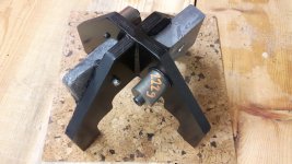
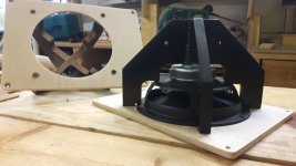
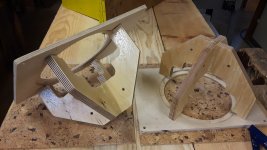
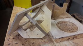
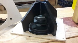
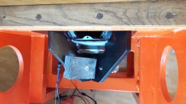
So playing with my new Burro Betsy fullrange to go into my OB I made an attachment, or holder, to hold the speakers onto the baffle. On this attachment I have som lead pieces and two smaller iron pieces, total of about 3kg. I figure the added mass on the back of the speaker makes for a more rigid fixture. I dunno, probably just a waste of time, but why not. I love creating much more to do than necessary.
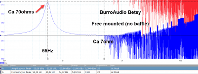
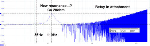
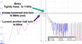
But I am a bit surprised at how much the resonance shifted by this. It was 55Hz when the speaker was alone in free air. But mounted on the small baffle and with the 3kg of mass behind it, the resonance is at 119Hz and much lower in max value, ca 20ohm, down from ca 70ohms at 55Hz in free air.
This normal?
Attachments
-
 betsyfreeair.png54.6 KB · Views: 291
 -
 20210620_201414.jpg284.7 KB · Views: 149
 -
 20210620_111315.jpg257 KB · Views: 137
 -
 20210621_000247.jpg304.7 KB · Views: 142
 -
 20210621_000237.jpg340 KB · Views: 173
 -
 20210619_151705.jpg211.6 KB · Views: 323
 -
 20210620_121802.jpg270.3 KB · Views: 273
 -
 20210620_121736.jpg288.5 KB · Views: 272
 -
 Betsyinattachment.png38.6 KB · Views: 302
Could you be measuring a suppressed resonance within the pressed steel basket itself?
Put some damping material like BluTak on the steel basket and see if it suppresses that 119Hz resonance, that will indicate where it is originating from.
C.M
Put some damping material like BluTak on the steel basket and see if it suppresses that 119Hz resonance, that will indicate where it is originating from.
C.M
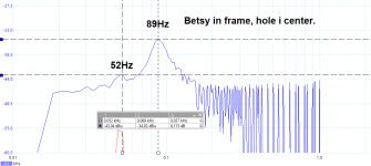
No it is the self resonance of the speaker...It is not a resonance in the basket or something like that, it is the Fs, the low end resonance. It has been shifted up, and I just wonder if it can shift that much. I loosened the screws half turn, and the resonance fell 5Hz, from 119Hz to 114Hz.
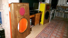
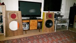
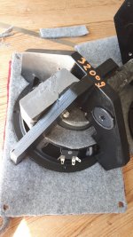
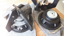
I had to give it a listen. The OB on the right is the under construction one with an old fostex 6", the left is the almost finished OB with the Betsy. Even with out the 15" woofer, the betsy sounds good right away. Looking forward to hear this when fully run in. The betsy seems to be slightly more efficient than the Fostex. Sitting in the center, the sound is slightly towards the betsy.
Attachments
With a weighted structure like that, I've always wondered how you put just the right - or "known" - coupling pressure on the driver magnet pole piece. Mechanically, that would be a big screw at the apex pressing on the pole piece with a torque spec.
I mean, is it "just touching" or "pushing pretty hard" when everything's battened down? Do you shim the area when assembling to adjust? Just curious how it's done.
I mean, is it "just touching" or "pushing pretty hard" when everything's battened down? Do you shim the area when assembling to adjust? Just curious how it's done.
Joe, you're talking about putting the basket structure under compressive stress. Now I don't think this activity is about basket resonance but if it were, I don't think compression is necessary. The only reason to feel that it is, would be so that it doesn't lose contact with the pressure point during a large excursion.. What it would need is reliable contact in either direction to some damping.
Adding mass too, wants a solid connection in both directions. As a reactive element it makes no sense to push the basket against the baffle unless that is also needed.
Adding mass too, wants a solid connection in both directions. As a reactive element it makes no sense to push the basket against the baffle unless that is also needed.
it is the Fs, the low end resonance. It has been shifted up, and I just wonder if it can shift that much.
Right, it's upper mass corner is ~2*Fs/Qts', so pretty close based on published specs, i.e. its Mmd/Mms has been annulled when it no longer rises with the trade-off of losing all that gain BW, so normally mass load it just enough to quell spurious resonances.
Over time, me, Dave p10, Scottmoose and others have recommended doing this, especially on inexpensive stamped frames that benefit most. Herbert Jeschke made an adjustable one and posted it; hope Dave still has it archived/post it.
The write-up, but the sketch didn't survive. 🙁
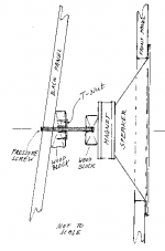
The Pressure Screw
This can be put in after you have already listened to your new speakers, but I found it audibly to great advantage. This is of course true because I used the RS drivers that have pressed steel bodies. Lowther drivers are likely to be rigid enough not to need that extra bracing. Same is probably true if you use cast frame speakers.
I used 3/8" threaded rod for the screw and cut it to proper length after trying it in place. Drill a 1/2" hole behind the speaker through the back panel. It should be vertical to the front panel and coincide with the speaker axis. Take about a foot of 2" by 3" lumber and slice it in two pieces lengthwise but at an 7 degree angle. Cut each sliced piece 8-3/4" or a little less long. That braces the rear panel across its width and will carry the T-nut for the screw. Cut a 2" by 2" by 1-1/2" block and drill a 1/2" hole in its middle but only 2/3 into its thickness. Glue that and center it onto the rear of the speaker magnet. I used Silicon glue for that. Loosely assemble the whole pressure screw jig and find out the screw length you need. Cut it with a hacksaw and cut a slot for the screw driver in the outer end. Fix the speaker well into its hole now and then turn the pressure screw against the magnet with some feeling and judgment. Not too hard but hard enough to withstand all expected vibrations. It works like the sound-post in a violin and helps keeping the magnet rigidly mounted.
Last edited:
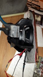
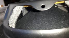
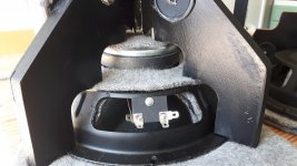
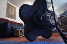
Some more details. I shimmed the driver using pieces of an old army wool blanket. This wool is very dense and about 1/4" (ca 6mm for modern folk) thick uncompressed. The frame is made so there is just a hair of clearance with no shimming, then it does not press on the basket at all. I actually managed this well, the gap is about a sheet of paper thick. (Usually I mess up and my cuts are nowhere what intended).
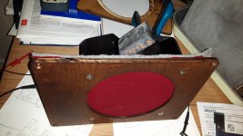
The front baffle piece is only 9mm birch ply, so the frame makes it rigid as well as adding the mass.
I have not listened to the Betsy with out the mass and frame, other than quickly held by some clamps on the floor, so I dont know if my frame and mass is an improvement. But I do think it is very solid and the Betsy sure sounds great even right away. So I am convinced this is good for this speaker, at least in an open baffle where the box is not there to hold it steady. Well, the OB does hold it, but anyways, why not have some more rigidity...
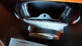
Edit... I placed two layers of wool inside the steel basket as shown, glued using sikaflex.
The front baffle piece is only 9mm birch ply, so the frame makes it rigid as well as adding the mass.
I have not listened to the Betsy with out the mass and frame, other than quickly held by some clamps on the floor, so I dont know if my frame and mass is an improvement. But I do think it is very solid and the Betsy sure sounds great even right away. So I am convinced this is good for this speaker, at least in an open baffle where the box is not there to hold it steady. Well, the OB does hold it, but anyways, why not have some more rigidity...
Edit... I placed two layers of wool inside the steel basket as shown, glued using sikaflex.
Attachments
-
 20210619_130126.jpg282.9 KB · Views: 78
 -
 20210619_130108.jpg279.4 KB · Views: 83
 -
 20210619_151715.jpg960.8 KB · Views: 88
 -
 20210621_074736.jpg317.4 KB · Views: 100
 -
 20210621_074802.jpg295 KB · Views: 103
 -
 20210621_074817.jpg229 KB · Views: 104
 -
 20210621_075904.jpg396.5 KB · Views: 92
 -
 20210621_075841.jpg442.8 KB · Views: 110
Last edited:
1. Do not use any iron near a magnetsom lead pieces and two smaller iron pieces, total of about 3kg.
This normal?
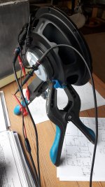
2. When measuring TSP I tried different ways of fixing the chassis. Always an additional peak appeared on the right side of the resonance, when I used also support from the back.. It was quite difficult to get a good curve.
3. To shift the resonance that much means the suspension has become harder or something limits the movement like an unvented air chamber.
4. Maybe was a measurement failure wrong sample rate of the sound card...
The measurement is with a pico scope. The iron pieces are far enough away I think but that is a good point. I will see if I have something else.
Btw there is only one peak. It looks good to me but it shifted up. The only restriction is the basket being held more firmly. I think...
Btw there is only one peak. It looks good to me but it shifted up. The only restriction is the basket being held more firmly. I think...
I will loosen the frame pressure a bit and see... perhaps find a spot between free resonance and the tightened hard resonace.
3. To shift the resonance that much means the suspension has become harder or something limits the movement like an unvented air chamber.
In other words: Does this driver have a small hole in the back that is blocked by your stiffening contraption ?
Regards
Charles
In other words: Does this driver have a small hole in the back that is blocked by your stiffening contraption ?
Regards
Charles
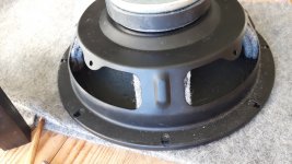
Aha...yes it does and yes it is blocked!
So if I drill out a hole in my frame...?
I just tried loosening the screws a bit more and the resonance is now at 88Hz.
Attachments
I will use this with a 15". The XO ca 250Hz. So does it matter? That the fs is higher? Does it affect the mid/highs?
Something is wrong with your measurements.
an Impedance plot is a straight line not this ripple above the resonance
looks like there is a high frequency oscillation
How did you measure it?
an Impedance plot is a straight line not this ripple above the resonance
looks like there is a high frequency oscillation
How did you measure it?
Last edited:
Something is wrong with your measurements.
an Impedance plot is a straight line not this ripple above the resonance
looks like there is a high frequency oscillation
How did you measure it?
It is the unfortunate feature of Pico Scopes. They do not belive in bode plots... or have not bothered.
The sweep is done settings on peak hold, then I manually select frequencies, as well as using the auto sweep. The resolution and steps are descrete and teh plot becomes rather poor. I can let it sweep for hours and it will eventually fill in all the gaps, but no time for that.
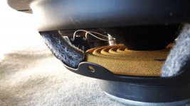
So I drilled out a center gap, and cut a little. Now the hole is free (free-er) only covered with one layer wool. The resonance is now at 89Hz or so, but there is a slight hump at 52Hz-ish that was not there before. 55Hz is the free air resonance...
Also I removed the iron pieces, they are marginal mass compared to the lead anyways.
Also I removed the iron pieces, they are marginal mass compared to the lead anyways.
Attachments

Over time, me, Dave p10, Scottmoose and others have recommended doing this, especially on inexpensive stamped frames that benefit most. Herbert Jeschke made an adjustable one and posted it; hope Dave still has it archived/post it.
The write-up, but the sketch didn't survive. 🙁
The Pressure Screw...
Dug it out of my archive: 🙂
Attachments
Thanks, interesting. In principle I think my contraption is similar. I dont have a rear panel, so made the frames instead. The frames give the back pressure.
Hi,
Weight at the back of the driver seems generally to be a good idea, if it is not bending the cheap steel sheet basket...
I used a 23 kg stainless steel counterweight at the back of my free-swinging AE Dipole 18, see pics, and liked it a lot better than without.
The pressure screw is also very good a lot better than any front mounted baskets.
But those measurements really look strange and don´t tell me anything, but maybe that´s just me...
I would suggest to buy or borrow a DATS and to measure again, with the DUT rigidly clamped (with non-magnetic material of course) and away from surfaces. That might give a better idea of what´s really going on...
Sorry if all that sounds a little bit disencouraging...
All the best
Mattes
Attachments
- Home
- Loudspeakers
- Multi-Way
- Weight/mass on back of speaker