Hey all,
Over past few months I've toyed around with the idea of building a tube amp from a kit, and just the other day this DIY built amp came up on craigslist.
The listing stated:
"This was built by a local hobbyist who passed away awhile back. I bought it from his estate. I tested it for a good 30min before purchase and it sounded absolutely wonderful. But, when I got it home it has a crackle. I can only assume something shook loose in transit. I have zero repair skills and have bought something else. I wish I could get it working. The 30min I tested it sounded magical."
When I got it home I plugged it in, connected it to some speakers, and all tubes lit up, there wasn't any crackling, however there is a low background hum, and more importantly a fairly loud oscillation which comes and goes, oddly when I push down firmly on the front of the amp by the volume knob I can get it to stop, although it seems to come back when music is on. Strange.
Now going from "I'd like to build a kit" to "I'm trying to troubleshoot a kit of man who has passed on" might be jumping into the deep end a little bit, but I guess we'll see if I'm biting off more than I can chew here.
So first, does anyone recognize this build? If it's a common design maybe I can find the schematic and work off that.
Secondly, where might one start to troubleshoot these problems? I would assume the oscillation first, and then maybe the hum after.
Thanks for your input!
Attachments
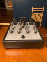
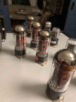
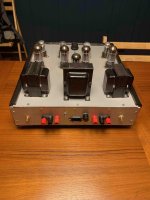
Looks like a push pull 6v6 output stage and 6sn7 pre stages. The other is a rectifier (one at the back).
A total of four 6v6 and four 6sn7 triodes (two per bottle) per channel - it’s not your average beginner model. The front looks like an LTP with a feedback from the output jacks then into a splitter but that could also be a cascode LTP.
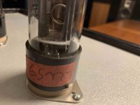
Can you take another photo of the front centre left tube - it looks like the getter has gone. If it’s white inside then that tube is dead.
A total of four 6v6 and four 6sn7 triodes (two per bottle) per channel - it’s not your average beginner model. The front looks like an LTP with a feedback from the output jacks then into a splitter but that could also be a cascode LTP.
Can you take another photo of the front centre left tube - it looks like the getter has gone. If it’s white inside then that tube is dead.
Last edited:
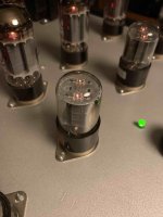
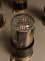

First I'm trying to see if they're both 6sn7 or a 6sn7+6sl7 (like a modified dynaco or a Williamson style amp). Second I'm trying to see if that patch on the side of the tube is metallic or powdery white. (filament glow doesn't mean the tube is good). Alternatively it could be a duff solder/screw connection - be *very* careful as it's high voltage (lethally so).
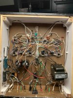
So there's a bit of a common wiring 'standard' they've used - first, the red marker on the socket shows the tag - separating between pin 1 and pin 8. Secondly the green is ground back to the star ground.
Secondly.. the 6v6 is a pentode (go me facepalm) .. so a single in each PP bottle.
Need more time to trace the pins but need to make lunch for the Mrs.
Last edited:
So tracing the pins, for each channel:
So inner front tube:
Input -> 6SN7-U1A -> 6SN7-U1B (the tube has a the link between pin 2 and pin 4).
Outer front tube as common cathode phase splitter:
U1B -> 6SN7-U2A - 6SN7-U2B (this has a grounded grid through a resistor).
Those then drive the 6V6S pentodes in a push pull configuration (the output trans is push pull) - interesting the screens are tied to power and the front end valves rather than using ultra-linear style from the output transformer taps.
Note that the phase splitter to pentode grid is anode rather than cathode follower, but that could be a misleading detail - would need to check more but this is close.. but yours has a simpler power supply arrangement.
6V6 PP1
Williamson:
williamson Valve Amplifier
More variants on this here: Acrosound,Altec, and Dynaco
Without going further, there doesn't seem to be a feedback except on the output secondary side. So I assume it's a Plain Jane Williamson.
The important bit is - getting it working without the crackers and hum etc.
Last edited:
Is the noise on one channel or both?
Does it make a noise (hum crackle) with the volume set to zero?
If you short the inputs (not the outputs!) and turn the amp up does it do the same?
What is disconcerting is the hum and touching the panel.. that sounds like a grounding issue and given the ground star is a simple nut.. possibly power down, drain caps and check the nut on that grounding star. Also check the output transformer grounds (one either side to the bolt).
Given there's no chassis grounding next to the power socket with a soldered lug.. BE VERY CAREFUL. If the bolt is loose then it's possible that the only path point is the top and your finger touching it.
Last edited:
Over time, I have bought several DIY tube amplifiers of this kind sold as "parts only" or "untested but it was working last time I tried it". They had glaring faults such as hum, noise, questionable electrical safety and don't look good. My experience suggests this approach:
- inspect and test it to see if it works at least partially. Check if the transformers are overheating. - you have already done this step.
- take measurements of high voltage power supply and cathode voltage of output tubes. This will show if the tubes are matched, will highlight weak tubes, will show if the tubes are operating at correct bias. You will also know voltage and currents available from the power supply.
- trace the schematic diagram and put it on paper. Check if it does make sense.
- disassemble the amplifier completely and check all the passive parts. Discard damaged/out of tolerance/questionable parts. If the transformers are vintage, disassemble the bells to check wire insulation.
- reassemble the amplifier in a new chassis, made of metal if possible, with solid core wire, proper solder terminal strips (such as Keystone 827), capacitor clamps, proper hardware, and correct transformer/choke placement.
This is faster, more reliable and way more fun that repairing the original circuit. Your purchase will never work reliably. Too many mechanically unsupported solder joints, covered with insulating spaghetti that makes them inaccessible to inspection. Ground stars made with unsoldered terminal lugs, kept togheter by bolts. Wire bundles and parts that are flapping in the breeze. Fiberboard chassis. This is a prototype, not a final product.
Last edited:
This is not likely to be something that you can safely fix as a first project, even with help.
The build is dangerous, and could have multiple problems that would require much experience
to deal with.
The build is dangerous, and could have multiple problems that would require much experience
to deal with.
As the solder work is a bit "unclean" i would check all connections on the tube sockets and check if all isolation tubing is covering the joints. Also check if the transformer is bolted strong enough as it looks like a ground wire is mounted on one of its bolts.
Please be carefull with this amp as it can bite you...
Please be carefull with this amp as it can bite you...
Is the chassis all wooden, including the top plate? It may need a metal case if it's not, in order to provide electrostatic shielding for the circuitry.
I appreciate all the insight from everyone! (and I agree that this might be a stretch to safely fix as a first project). And I'll definitely heed the calls to be cautious and will be careful with this thing.
The chassis is entirely wooden, top plate included.
Here's a brief video of the oscillation. This comes on with the amp at zero volume. The hum that starts in the video is when I turn the volume up to full.
Amp Oscillation - YouTube
Now, if I can't safely fix this, is there enough going right with this amp that someone experienced COULD fix it? Does it need a complete tear down? Is that something I could potentially do if I was meticulous about it, or am I maybe just in too deep?
Again, thank you all so much for your input!
That sounds like motorboating. I would disconnect the feedback and see what it does but more likely I suspect it's a power supply problem.
Now, if I can't safely fix this, is there enough going right with this amp that someone experienced COULD fix it?
Does it need a complete tear down? Is that something I could potentially do if I was meticulous about it,
or am I maybe just in too deep?
If you find an experienced hobbyist locally, he could help you learn and fix this safely.
But all the circuitry would have to be transferred to a metal chassis,
or at least a metal top plate.
You might need to replace capacitors. I would test them. Disconnect and test them one by one. If you have new, fresh capacitors just replace them. New, fresh means manufacured in recent times. No vintage stuff, especially for electrolytics.....
This amplifier seems to have been built with transformers reclaimed from a '60 console and other scavenged parts. The Hammond choke is dated 2002. Main filter capacitors are of the kind usually fitted on guitar amplifiers and may still be good. I would loosen the main ground nut, apply a little bit of deoxit, then thighten the nut again. I don't see a bleeding resistor on the high voltage supply, capacitors may be still charged. Be careful. It's a classic circuit with very few parts, easy to rebuild, no need to struggle searching faults due to bad assembly choices.
If you find an experienced hobbyist locally, he could help you learn and fix this safely.
But all the circuitry would have to be transferred to a metal chassis,
or at least a metal top plate.
Do most folks DIY their own chassis or is that something fairly easy to acquire??
This amplifier seems to have been built with transformers reclaimed from a '60 console and other scavenged parts. The Hammond choke is dated 2002. Main filter capacitors are of the kind usually fitted on guitar amplifiers and may still be good. I would loosen the main ground nut, apply a little bit of deoxit, then thighten the nut again. I don't see a bleeding resistor on the high voltage supply, capacitors may be still charged. Be careful. It's a classic circuit with very few parts, easy to rebuild, no need to struggle searching faults due to bad assembly choices.
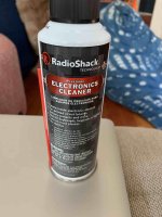
I have this RadioShack cleaner I just found with all my audio stuff, should I give it a shot with this, or order some proper deoxit?
Attachments
- Home
- Amplifiers
- Tubes / Valves
- Is this a common DIY build?