I thought you always used a Rod Coleman regulated supply. Is there some reason why that won't work for this?
That's just for DHTs. This is for regular heaters which need to be DC heated with regulation.
This thread is being really useful. I've rigged up a circuit and it works well in testing.
Seems to me that this is a case of breadboarding all the parts and seeing how hot they get. I went with 2 x 6v transformers giving me 7.8v DC each with Schottkys + 10,000uF, then 2x LM338. One supply per tube. Heatsinks are 5 x 5 x 2.5cm.
Seems to me that this is a case of breadboarding all the parts and seeing how hot they get. I went with 2 x 6v transformers giving me 7.8v DC each with Schottkys + 10,000uF, then 2x LM338. One supply per tube. Heatsinks are 5 x 5 x 2.5cm.
DC-DC LM2596 3A Buck Adjustable Step-down - no heatsink needed.
DC-DC LM2596 3A Buck Adjustable Step-down Power Supply Modules Converter | eBay
I use it in my 2x4p1l or 2x6e5p amp. No problems.
No LM338 has way too much dropout voltage. It will not work OK for 6.3V output at considerable load. Please measure what the results are as it is not possible. Even when LM338 would have a dropout voltage of 1.5V it wouldn't work. 7.8V - 1.5V = 6.3V. That leaves exactly 0 margin for the ripple voltage and mains voltage fluctuations .....And LM338 has way higher dropout voltage.... With uLDO and LT4320 it is possible within acceptable margins.
This is for 4v tubes. I appreciate your suggestion of LT4320 and will look into that.
This thread is being really useful. I've rigged up a circuit and it works well in testing.
Seems to me that this is a case of breadboarding all the parts and seeing how hot they get. I went with 2 x 6v transformers giving me 7.8v DC each with Schottkys + 10,000uF, then 2x LM338. One supply per tube. Heatsinks are 5 x 5 x 2.5cm.
Yes I noticed I calculated for 6.3V and you need 4V 🙂 If the circuit is built for 4V (please write unit values in capitals) it is very very tight with LM338. Dropout voltage of LM338 is specified at 1.5 - 2.5V depending on output current. We must calculate worst case.
7.8V - 2.5V dropout = 5.3V. That leaves only 1.3V left for ripple voltage and mains fluctuations. I think upgrading to LT1084 or, even better, an uLDO is advisable.
Last edited:
If that is built for 4V (please write names with capitals) it is very very tight with LM338. 7.8V - 2.5V dropout = 5.3V. That leaves only 1.3V left for ripple voltage and mains fluctuations. I think upgrading to LT1084 is advisable.
Thanks for that. I have some LT1084.
That will work, the current version can not work reliably at the set output voltage. LT1084 has a dropout voltage from 1 to 1.5V at full load. Still tight depending on start up current etc. but already better than with LM338 as you gain 1V 🙂
I think I would go for LT1764 for absolute trouble free functioning in all possible scenarios if the 3A maximum is allowable. If you will use LT1084 please use the bypass capacitor at the ADJ pin for better ripple reduction AND soft startup!
In all cases you will need 10,000 µF caps as a minimum to keep ripple low enough. Because of a project I have become an experienced "minimum calculator" although it is officially not good design practice. Still fun when it gets the job done at minimal dissipation and, apart from some workarounds, no real showstopping issues that theory predicted. I even went as far to select the Schottky diodes with lowest Vf. Chances for success go up considerably when using LT4320 and the then tens of mV range dropout voltage. It then is solid engineering again.
Last edited:
I've never had issues with AC on indirectly heated tubes. I mostly see people using DC in phono stages. Did you try AC and have problems?That's just for DHTs. This is for regular heaters which need to be DC heated with regulation.
I've been using a little Meanwell SMPS to heat 26s and other DHTs in my current project and it seems to work well.
Here's one that might work for you. Output voltage is adjustable to some degree and various wattage ratings are available.
Blocked
I added an LC section to the output for additional filtering using this and a 22,000uf cap and make any other adjustments with a dropping resistor if needed. You would need something with a higher current rating, though you might not really need any additional filtering.
Blocked
Easy turnkey solution.
Not sure why the links read "Blocked" but when I click them they work.
The Meanwell SMPS I linked is model LRS-35-5 and the choke is a Triad C-56-U.
Last edited:
Or a capacitor Multiplier, I've loaded this ESP circuit to 2 amps on the bench and the pass transistor barely gets warm un-sinked, while the dummy load got plenty hot. I left it running overnight at 1A and it stayed stable all night. No regulation, but if you trim it up to deliver 3% under your tube voltage at your closed loop current you'll have some room for mains variations upwards. Cap multipliers work best with non-varying loads which is exactly what a filament is. Not having to regulate anything then the transistor stays cool. And the resistors in the filter chain can be small 1/4 watters. Just build the positive leg below.

error:
1. 6.3 x 1.414 ~= 8.8V peak, not counting the rectifier drop (Schottky Bridge?).
Was already corrected....still 1V was lost somewhere as anyjevans ended up with 7.8V but maybe this was under load. Also LT1764 with 0.35V dropout voltage was already suggested but its maximum output current is 3A which may be tight with 2.5A average load current.
For reliable operation one has to max out on least dropout voltage of the regulator, overdimensioned filter capacitors for lowest ripple voltage and lowest Vf of the rectifiers. With LT4320 one can't go wrong... at a price.
For reliable operation one has to max out on least dropout voltage of the regulator, overdimensioned filter capacitors for lowest ripple voltage and lowest Vf of the rectifiers. With LT4320 one can't go wrong... at a price.
Last edited:
This will work and have way less voltage drop than the other suggestions...
https://www.mouser.ca/ProductDetail/Analog-Devices/LT1764AETPBF?qs=ytflclh7QUUyyj6j%2BMiGLQ==
LT1764
https://www.mouser.ca/ProductDetail/Analog-Devices/LT1764AETPBF?qs=ytflclh7QUUyyj6j%2BMiGLQ==
LT1764
Always wondered if you could adapt the LT4320 to higher voltages by dividing down the input to the chip…
....still 1V was lost somewhere as andyjevans ended up with 7.8V but maybe this was under load. Also LT1764 with 0.35V dropout voltage was already suggested but its maximum output current is 3A which may be tight with 2.5A average load current.
7.8V was under load. The load current is nominally 2V so LT1764 would be OK I imagine. It works fine with LM338 and no doubt better with LT1084. In what way is LT1084 preferable to LM1084?
Did you check what is happening with an oscilloscope? It may be close to regulating on and off 🙂
Current will be in Ampère I guess. 2A is nothing to worry about.
LT1084 is the Linear Technology version which is AFAIK the original and as I stock those I use the type number of the version I use (don't buy from Ebay as fakes are around). LT1764 is a fine regulator with highest chance of issueless operation as it is an uLDO.
Last edited:
Did you measure/check with an oscilloscope?
Yes.
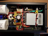
The metal box is a 6.3V 4A resonant switching supply block. Being resonant, it produces low EMI for a SMPS.
I use them in every amp for indirect heating. It has soft start and overload protection. It takes little space in the chassis, produces negligible heat and doesn't need a big transformer/rectifiers/etc.
The scope measure is under load (5mV/div and 5µs/div, 1x probe), the PSU supplies 3.1A to this 6AS7G headphone amp.
The heating wires are of course tightly twisted, there is a ceramic cap between the tube's pins and the supply is elevated via a voltage divider as an extra precaution against heater-cathode leakage.
Attachments
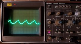
Ha ha I was confused as the previous post was about the linear PSU of anyjevans 🙂 The linear PSU should be checked as the point where the regulator won't regulate anymore is too close. The difference between the lowest point of the ripple voltage and the minimum required input voltage of the regulator is of interest. My educated guess is that is hovers under less than 0.8V which is tight.
Yes that switcher does not look bad at all, well quite OK actually, but bandwidth of the oscilloscope is not enough I think. A worthy alternative to those that have no fear of SMPS. I am confused again as it is not the LM2596 PSU you mentioned and of which I asked if you had measured it, that was this one:
DC-DC LM2596 3A Buck Adjustable Step-down Power Supply Modules Converter | eBay
I am not so sure if that one is as clean as the metal box one. There is no connection of V- to PE/outside cover? To end confusion: the 6.3V metal box one.
Last edited:
Simple question. What would you use for a basic regulated DC heater supply? Right now I need about 2.5A at 4v but it would be good to have some general ideas.
AC isn't possible since I'm using dropper resistors from a 6v transformer and possible tubes to be used are 4v but have different currents, so the dropper resistors give different results.
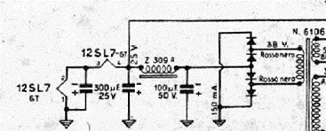
I assume an LM338 is a simple solution. Do you need the input and output caps in the attached circuit, or could it be simplified if supply caps are inside 6" (says so in the data)? I'd be using a 6v transformer.
Using online calculators, with a 240R in R1 looks like you need 520R in R2 for 4v. Not sure what wattage though.
Suggestions for a heat sink size for 2.5A out?
This is going to sound nasty.. non-conventional.
Look at this:
Mini 3A DC-DC Converter Adjustable Step down Supply Module replace LM2596s | eBay
these are cheaper that I could ever hope to build them. Switching frequency is 1Mhz.
I bought a few for a pittance.. they were all GOOD. I use some Loctite on the tiny pot after setting it.
Over 2 years and I haven't had one fail yet.. There are others out there too. Some have heat sinks.. some have different switching frequencies. Just check out the specs and test them a bit first.
Ian
- Home
- Amplifiers
- Tubes / Valves
- Regulated DC heater supply