I’m going to attempt a design with the Satori TW29DN-B tweeter in an active system (miniDSP), and I want to implement a series capacitor as protection in the event that there is a power surge or breaker trip event that sends unfiltered signal to the driver. I’m going to go with the camp that recommends a value at fs + 200 Hz as the target corner frequency. My question is in regard to calculating the correct capacitor value. Do I want to go with the nominal impedance of the driver, or do I want to target the impedance at the cross point?
Thanks in advance.
Thanks in advance.
I would perform an impedance sweep of the tweeter and measure the frequency response of the tweeter. Choose a capacitor value based upon the measured impedance of the tweeter at the target frequency. Connect the capacitor and measure the frequency response again to ensure that the behavior is what you expect. I'm not aware of the "fs +200Hz" idea. That may be pretty high and impact the slope of your active filter.
Thanks for the insight bourbon-neat. The fs is 650 Hz, so the target would be 850. Looking at the Satori impedance plot, it looks like 850 Hz is around 8'ish Ohm.
Alternatively, I could also pick up a couple capacitors that align with targeted cross points to integrate it into the overlayed/summed filter. I'm crossing this to a 6.5" driver and want to cross a low as possible without straining the tweeter. I'm thinking 1800 is doable at the levels that I listen. I'm guessing that I'll end up somewhere in that neighborhood.
Alternatively, I could also pick up a couple capacitors that align with targeted cross points to integrate it into the overlayed/summed filter. I'm crossing this to a 6.5" driver and want to cross a low as possible without straining the tweeter. I'm thinking 1800 is doable at the levels that I listen. I'm guessing that I'll end up somewhere in that neighborhood.
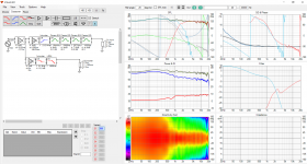
To get best results I suggest doing full set of polar response measurements and use VituixCAD to simulate the xover. You'll see exactly what size capacitor and DSP settings are needed to get the acoustic response as good as it can be 😉 Good measurements are the key, there is guide in the VituixCAD download page. You can get into the ballpark without but no guessing needed with good data and simulator.
kimmosaunisto.net - VituixCAD
kimmosaunisto.net - VituixCAD
Last edited:
I would choose this way, this capacitor may as well be approximately the smallest value needed.integrate it into the overlayed/summed filter.
Large, if you want to avoid phase shift in the crossover region. Btw, I always mount tweeters directly after the power amp, up to hundreds of Watts if that is practical. Never had an issue. The most likely scenario is the case where an RCA plug half connects anyways. This can kill tweeters regardless of protection because of HF content. Better invest in balanced connections, where this will never happen by design
To get best results I suggest doing full set of polar response measurements and use VituixCAD to simulate the xover. You'll see exactly what size capacitor and DSP settings are needed to get the acoustic response as good as it can be 😉 Good measurements are the key, there is guide in the VituixCAD download page. You can get into the ballpark without but no guessing needed with good data and simulator.
kimmosaunisto.net - VituixCAD
tmuikku, this is very good advice. I think that I will do this.
I don't know about the particular system, but as an example I recently tried to help fellow member with crossover simulation and the compression driver high pass called for ~21kHz 1st order 😀 This aligned the phase nicely around crossover. High pass lower down wasn't as good alignment. Wouldn't have guessed beforehand but I'm not expert in the field so no wonder. The example is a quick one with digital filters but could have used single capacitor as well (I think, no impedance data was available).
Point being it is very easy to see what the system calls for after the data is fed into the simulation program. Sim the miniDSP filters along with the series capacitor and the whole situation is clearly seen. Helps to get best possible outcome without guessing about it. Let your loudspeaker system tell what is required, not the DIY group 😉
Point being it is very easy to see what the system calls for after the data is fed into the simulation program. Sim the miniDSP filters along with the series capacitor and the whole situation is clearly seen. Helps to get best possible outcome without guessing about it. Let your loudspeaker system tell what is required, not the DIY group 😉
Attachments
Last edited:
I agree with Vacuphile, Larger is better than smaller.
In my own experiments I use a 4th order active HP with capacitor to protect the driver from any DC that may arise.
To minimise phase changes over the XO point at 2.5kHz, I needed to use 22 to 33uF.
In my own experiments I use a 4th order active HP with capacitor to protect the driver from any DC that may arise.
To minimise phase changes over the XO point at 2.5kHz, I needed to use 22 to 33uF.
I ended up ordering the tweeters and didn't get capacitors. When I get them in hand I will measure them and test a number of electrical 4th order cross points with the mids to see where it integrates well. When I land on a cross frequency I will then order the appropriate capacitor that allows integration with a 3rd order electrical filter. I will also try the low frequency capacitor with an electrical 4th order filter simply to see which sounds and measures better. It seems like a good opportunity to see for myself the pros and cons of each approach.
I appreciate everyone's input on the topic. Thank you.
I appreciate everyone's input on the topic. Thank you.
No. Larger capacitors can have significant charge/discharge times and low frequencies associated with thumps or various other anomalies could still damage a tweeter via those charging currents.....in the odd circumstance. It is unlikely though.I agree with Vacuphile, Larger is better than smaller.
In my own experiments I use a 4th order active HP with capacitor to protect the driver from any DC that may arise.
To minimize phase changes over the XO point at 2.5kHz, I needed to use 22 to 33uF.
If adding a capacitor is the choice, then incorporate it right into your desired roll-off characteristic. That's the best approach and it uses a smaller value capacitor
Dave.
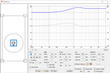
Animation with ideal drivers and simulated baffle. It is ~1" tweeter and ~4" woofer on a small baffle. 2kHz LR4 crossover on DSP and varying cap size on the tweeter. In this case a 50uF cap doesn't seem to have too much influence on the response anymore. If smaller cap is used, the high pass filter on the DSP needs adjustment.
The ideal drivers in the attached simulation have flat frequency response 20-20kHz so no acoustic high pass on the driver itself. In real world there is acoustic high pass on the driver in addition to the DSP and the cap filters and they all combine to an acoustic slope. DSP is easy to adjust so one might use capacitor that is readily available. Otherwise it makes sense to use smallest cap possible to save some currency units.
ps. the frequency response ripple in the attachment is due to simulated baffle diffraction. Diffraction and other issues can be analyzed and addressed (or not) quite easily in the simulator as well. Kind of promoting VituixCAD since it is quite awesome tool. 😀
Attachments
Last edited:
- Home
- Loudspeakers
- Multi-Way
- Tweeter Series Capacitor in Active System - Choosing Value