Possibly. I said Qts because it's the lower limit for Qtc. In post 5 I mentioned that I'm talking about transient response of frequencies above where box tuning affects it
I wrote it and thought I posted it right after yours only to find I didn't, so without reading the newer responses before the belated posting, didn't see this or the thread in general go 'off the rails' til now.........
Above Fhm, the driver's 'speed' [BW] governs its HF response, which in turn is governed by its inductance, so need to quit calling it 'transient response' as we're dealing with amplitude, phase, which must be flat for accurate reproduction.
I was not referring to the box but to the room (hope it’s not the big grey animal in the middle of it here). But I suggest you dive into Wolfgang Klippel’s work (can’t help but thinking you’re still on the track of tone bursts)...I'll say again, this is (and always has been, clarified in post 5) regarding frequencies above the ones affected by box volume
I think was is missing from the discussion is the limiting factors like the voice coil getting out of the magnetic field, the mechanical limits of the spider and the surround, etc. These, as I understand, limit the maximum excursion of the cone and also cause non-linearity to appear when you approach those limits.
Jan
Jan
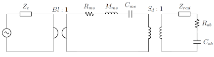
Low end behaviour of a woofer -incl that behaviour in various enclosures- can be described with the so called lumped element parameter model.
That is why woofers have (TS) parameters.
This LE model, which can be be more refined with additional elements for e.g. VC temperature changes, forms the basis for all simulators. You do not have to measure different woofers for their low end behaviour: you can simply plug their TS parameters in any decent simulator. There is nothing magic about al that and "speed" does not come into play as others have explained here.
The upper limit of the passband is a whole different kettle of fish: that is very driver, cone profile, material, thickness, termination etc. etc., specific.
Can that also be modelled? Yes, but only by very advanced (e.g. FEA) modelling.
Attachments
No.
GM means a Total Q, Qb, Box Q of 0.5.
I think (and speaking for him) GM may be speaking about both Qb and Qts.
He has vastly more understanding than I, and I'm sure will correct my errors.
Correct on all counts, so maybe the gap's not so vast. 😉
Put another way, the permanent magnet is only so strong. If you drop a weighted coil into a motor (say 100g) and give it a pulse at 10v, it shoots out with a velocity of x. Increase the voltage from 10v to 20 to 30, continuing to 1000, each time it shoots out faster. But, at some point, the speed is not limited by the voltage anymore, but the magnet that the coil is using to push off of. (Ignore air resistance, the coil weighs 100g, not a 12" cone)
This is what I'm referring to in 23.
Does it work as I described above, or does force continue increasing with voltage at the same rate indefinitely?
I'm not sure I follow, so will just say again that the driver's 'speed' governs its HF response, so when it needs to reproduce a 'fast' [high Q] transient [not transient response], its rise/decay rate will be dependent on power required, inductance, so if inductance is rolling it off, then more power is required to follow the transient, which in turn may be clipped by either the amp and/or inductance, i.e. a 'slow' performing driver.
WRT to defining this as some sort of slew rate, seems like we already have one in that sound power falls at 1/f, so its 'slew rate' would be the frequency response's decay rate, i.e. dB/octave slope.
Indefinitely? Obviously not, but until that point yes.... This is why I mentioned a separation between small signal analysis and non-linear behaviour... and the idea of the stronger magnet, would change things at low levels too, altering the result but not allowing it to go on indefinitely.
Ordinarily, doubling the drive Voltage doubles the pressure and quadrupling the drive Voltage quadruples the pressure.
Isn't doubling pressure +3db?
I wrote it and thought I posted it right after yours only to find I didn't, so without reading the newer responses before the belated posting, didn't see this or the thread in general go 'off the rails' til now.........
Above Fhm, the driver's 'speed' [BW] governs its HF response, which in turn is governed by its inductance, so need to quit calling it 'transient response' as we're dealing with amplitude, phase, which must be flat for accurate reproduction.
Yes, I know, I said in a recent post it should be called "magnitude of driver response to transients in signals"
I gave an example in the same post, I want to modify and expand on it a bit to better communicate my thoughts:
For a woofer, a 3 second sinusoidal tone at 300 and 2000hz is done at 1w and 100w. 100w is chosen because the driver's electrical power rating is 50w rms. 3 seconds is chosen because this isn't supposed to be a tone burst and thermal compression is intended to be kept to a minimum
If the driver is 1% efficient at both 300 and 2000hz at 1w, and 0.92% efficient at 300hz/100w and 0.90% efficient at 2000hz/100w, then the driver has an overall 91% magnitude response to transient signals within its power limit.
I assigned the parameter "Rt"
Rt low = 92
Rt high = 90
Rt total =91
The closer to 100, the better the driver can reproduce high level intermittent sounds at full level
This compression, is any of it related to the strength of the magnet? I know other things would be contributing to the increased losses at the higher level, like thermal and mechanical, but...
Is any of it from the size of the magnet? Would doubling the magnetic field in the gap and leaving the rest of the driver unchanged, make it 2% efficient at 300 and 2000hz at 1w, and 1.84% and 1.80% efficient at 300 and 2000hz at 100w?
Would efficiency at 2000hz/100w come closer to matching 300hz/100w with the bigger magnet?
I'm not sure I follow, so will just say again that the driver's 'speed' governs its HF response, so when it needs to reproduce a 'fast' [high Q] transient [not transient response], its rise/decay rate will be dependent on power required, inductance, so if inductance is rolling it off, then more power is required to follow the transient, which in turn may be clipped by either the amp and/or inductance, i.e. a 'slow' performing driver.
WRT to defining this as some sort of slew rate, seems like we already have one in that sound power falls at 1/f, so its 'slew rate' would be the frequency response's decay rate, i.e. dB/octave slope.
The upper rolloff from inductance is something I recognize, and I think the magnetic effect I'm trying to quantify would behave similarly. Instead of the coil appearing to have more resistance, the magnet would appear weaker
Last edited:
...only by very advanced (e.g. FEA) modelling.
I like the picture you posted. Electrical equivalent circuits are awesome
It might be important to note, efficiency is at 100 watts, not at the voltage assumed to be required for 100 watts from the impedance curve derived from the current draw at 2.83v
It's not clear to me why you would abuse a 50W rated driver with 100W signal, even for 3s. Otherwise I think you'll find drivers to be pretty linear devices. You could perform the test with pink noise, bandpass shaped with the intended range of use. Or a frequency sweep. The HifiCompass site actually shows the response of quite some drivers with voltage inputs up to 16V RMS. The few I checked act 'pretty' linear with each voltage doubling resulting in +6dB (as it should).
Last edited:
It's not clear to me why you would abuse a 50W rated driver with 100W signal, even for 3s. Otherwise I think you'll find drivers to be pretty linear devices. You could perform the test with pink noise, bandpass shaped with the intended range of use. Or a frequency sweep. The HifiCompass site actually shows the response of quite some drivers with voltage inputs up to 16V RMS. The few I checked act 'pretty' linear with each voltage doubling resulting in +6dB (as it should).
50rms is 100 peak, everyone knows this. Giving a driver it's peak power for 3 seconds should not damage it, especially if the tones start 3 octaves above resonance and only get higher. Why you would call this abuse is beyond me. It's supposed to be a measurement of performance near the highest level the driver should/will be used at, so of course the level is high. Not sure why it isn't clear to you when I said "3 seconds is chosen because this isn't supposed to be a tone burst and thermal compression is intended to be kept to a minimum"
16 volts rms is a good, not great, metric. Better than 2.83, but hardly up at the level of transients. Unless 100db/w or low listening levels in medium to small rooms
You didn't address any of my post...
Last edited:
Consider how sometimes a manufacturer will use 2 midranges instead of 1. What does this do? Among other things, it usually improves the definition (scale) of transients, even at levels far below xmax. From the doubling of BI, Mms, and surface area. Just keep it in mind while thinking. And the last of my post #47 (preceeding sentences required reading) restated below:
The magnetic effect I'm trying to quantify would behave similarly to inductance, but instead of the coil appearing to have more resistance at higher frequencies, the magnetic field would appear weaker at higher (signal) levels.
If force doesn't increase with voltage at a constant rate to infinity (I think it's been established it doesnt),
the higher the signal, the weaker the field becomes in relation to it. Meaning more compression will result at higher level signals. It's just how much of an impact does this have on the amplitude of transients in audio signals at various listening levels, and how can it be countered? And how can it be quantified? Separately from induction, internal damping from things like aluminum VC, etc
Last edited:
50W RMS is a first order iteration of how much a transducer can handle. And lots of manufacturers use their own kind of iteration. IEC 268-5 seems to be common though. But (even) IEC 268-5 doesn't imply one can apply the rated power at the unit, disregarding everything else.Giving a driver it's peak power for 3 seconds should not damage it, especially if the tones start 3 octaves above resonance and only get higher. Why you would call this abuse is beyond me. It's supposed to be a measurement of performance near the highest level the driver should/will be used at, so of course the level is high. Not sure why it isn't clear to you when I said "3 seconds is chosen because this isn't supposed to be a tone burst and thermal compression is intended to be kept to a minimum"
16 volts rms is a good, not great, metric. Better than 2.83, but hardly up at the level of transients. Unless 100db/w or low listening levels in medium to small rooms
You didn't address any of my post...
As for your points: I understand you want to evaluate the transducer behavior at levels where the motor (magnet plus voice coil and suspension) becomes nonlinear. Or even the whole speaker starts behaving badly. For analysis of this I already pointed to Klippel (been there?). Nonlinear behavior in this domain is not that dependent of frequency, apart mainly from the fact that, due to higher radiation impedance at high frequencies, the required power to reach a certain excursion at those frequencies imposes other (thermal) effects on the output.
A lot of (pro) manufacturers determine the maximum excursion based on distortion figures on broadband signals (which to me makes more sense than measuring the sole sound pressure level by the way). As SPL is directly related to excursion, all else being equal (eg no cone breakups), the linearity of that excursion would be of your interest.
Only with a sine wave and still, that only relates to the mean power vs. the max power in a cycle. It's not that you can pump up the voltage on a sine wave with 1,4x and think that 3s duration won't harm.50rms is 100 peak, everyone knows this.
Conclusion: I don't get what you are set for. Another measuring protocol? Get to know the existing ones first. Or just pre-work for a loudspeaker design? In that case it would be more helpful if you decide on your design goals (as in max SPL with a certain acceptable distortion level on a certain frequency passband), figure out what the dynamic range is of the music in question and then draw conclusions. Most home hifi systems struggle producing anything near 110dB (flat, within 40Hz to 20k), but that actually is quite a lot. And my ears start distorting with such figures too...
When tuning vented enclosures, all losses have to be accounted for. Before they were, the performance of designs was limited and not entirely predictable. Good designs were accomplished on occasion though, usually when the losses unaccounted for, were minimal.
I believe the loss I'm describing isn't accounted for and if it was, results of design would be more predictable, and great performance wouldn't have to be exclusive to overdesigned drivers which make this loss small enough to not be a limiting factor.
Regarding your reply, yes the rms power is a "first order iteration"... but it's just the simplified term I used to continue the discussion without excessive words. We can't go through every thing, every time, in every post. Nothing would ever get done. Drivers have two maximum levels: the electrical power maximum (thermally limited), and the excursion limited power maximum (mechanically limited).
Maximum electrical power for 3 seconds beginning at a minimum of ~3 octaves above resonance will not cause mechanical damage or thermal damage to a driver. Mechanical limits won't be reached, and there simply isn't time for the temperature to rise to a damaging level. Please don't nitpick irrelevant points.
Yes, it's important for measurement purposes that the frequency is low enough to be away from cone breakup - it's been brought up and taken into consideration already. Going over it (and other points) again like they haven't been discussed and accounted for, just isn't productive.
I get it would be hard to isolate from all the other non-linearities of drivers, but it's present. So instead of listing them all, imagine a driver designed ideally to measure it. An underhung design with a very even magnetic field in its gap is a good starting point.
Edit: I'll be looking into Klippel this evening
Edit: I'll be looking into Klippel this evening
Last edited:
Well, in theory I guess you could saturate the magnet assembly with a high enough current and a proficient coil. But with the power limits of voice coils that won’t happen.. Long before that the voice coil will have deceased. Until saturation motor systems are pretty linear. That leaves us with excursion issues. Static or dynamic doesn’t matter here, the force is the same integral over the conductor in the magnetic field. And that is where Klippel comes in.
How will you apprehend the output by the way? I only read something about SPL related to input voltage. The RMS value actually rises faster than the peak SPL when the cone reaches it’s limits, because of excessive HD products.
How will you apprehend the output by the way? I only read something about SPL related to input voltage. The RMS value actually rises faster than the peak SPL when the cone reaches it’s limits, because of excessive HD products.
Well, in theory I guess you could saturate the magnet assembly with a high enough current and a proficient coil. But with the power limits of voice coils that won’t happen.. Long before that the voice coil will have deceased. Until saturation motor systems are pretty linear. That leaves us with excursion issues. Static or dynamic doesn’t matter here, the force is the same integral over the conductor in the magnetic field. And that is where Klippel comes in.
How will you apprehend the output by the way? I only read something about SPL related to input voltage. The RMS value actually rises faster than the peak SPL when the cone reaches it’s limits, because of excessive HD products.
I guess part of what I'll look into will be the behaviour of motor systems before magnetic saturation occurs. If what you say is true, and more current is required to reach saturation than a voice coil can endure, and that motor strength is degraded only after saturation, then the slew rate (defined as slippage here) is infinite for practical purposes and the discussion would be over.
I initially suggested the frequency to be used for this measurement should have the wavelength ~1.5 cone diameter to avoid beaming and xmax. If a cone can't hold its shape well enough for a short +3db signal at 600hz 5", 300hz 10", 200hz 15" etc., then the driver is junk and doesn't deserve its power rating
Last edited:
Yes, I know, I said in a recent post it should be called "magnitude of driver response to transients in signals"
This compression, is any of it related to the strength of the magnet?
Is any of it from the size of the magnet?
The upper rolloff from inductance is something I recognize, and I think the magnetic effect I'm trying to quantify would behave similarly. Instead of the coil appearing to have more resistance, the magnet would appear weaker
Sorry, my tired eyes glazed over this post, seeing nothing that resembled what I ultimately posted or seem to understand the fundamentals of driver design.
Regardless, both could be, i.e. the more the magnet blocks air flow and/or the material type can act as an insulator [ferrite/'mud'] the more likely I^2T lets its smoke out with the magnet none the wiser. 🙁
AlNiCo [most familiar with grade 5] OTOH will up to a point act as a heat sink, temporarily losing some of its field strength, so BIB [bigger is better] rules.
The newer, much more powerful, magnets allow much more design freedom, so for best overall performance the best option short of the pioneer's field coils.
At this point it's high time we relegate the spiders to the history books for any serious HIFI/HT/Prosound app and use multi layer VCs centered on roller bearings moving through 'staged' magnets like Babb did in the '70s to get a super high, linear, Xmax.
Unfortunately, DC Gold currently holds the patents and would be surprised if they would share anymore than Babb did.
I'll leave the rest of your post to others more qualified and still don't see how you're going to arrive at some sort of transient 'slew rate'/whatever considering the number of additional variables I've presented you with, but at least they prove your assumption that 'things' aren't always what they seem to be. 😉
Just wondered what exactly you are going to measure. I wasn’t referring to cone breakup. What kind of waveform analysis/spectral analysis do you have in mind, as measuring the unweighted SPL with a SPL meter won’t workI initially suggested the frequency to be used for this measurement should have the wavelength ~1.5 cone diameter to avoid beaming and xmax. If a cone can't hold its shape well enough for a short +3db signal at 600hz 5", 300hz 10", 200hz 15" etc., then the driver is junk and doesn't deserve its power rating
Come to think of it, you could use a dual channel scope. Comparing the in and out signals could work, though setting that up requires two channel triggering or one channel storage.
Last edited:
- Home
- Loudspeakers
- Multi-Way
- Importance of slew rate and transient response