Hi Everyone,
I recently picked up this 6B4G push pull amplifier. I normally just stick to single ended amps but, I thought this would be fun to play with. My thoughts were that the extra power would give me the ability to use less efficient speakers and I love the sound of 2A3/6B4G's. The things I've noticed with it so far is that one of the output 6B4G pairs are more challenging to dial in the bias (I'm thinking that they're poorly matched or perhaps one of the tubes is on its way out?) the other anomaly I've noticed is that the overall volume will dip slightly, as if the volume was just turned down, and then in a few minutes come back up again (both channels). I'm going to check my other gear to make sure it isn't a problem with what's feeding it.
I'm currently debating about splitting the amp into two monoblocks. I was wondering what people think of the current circuit. If I should keep it or modify it.
Attachments
Is this a commercial amp or someone else's homebrew?
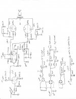
I see a number of problems as drawn. Did you copy the schematic from somewhere or did you trace the circuit yourself?
I see a number of problems as drawn. Did you copy the schematic from somewhere or did you trace the circuit yourself?
I am trying to knock my head around and have the coffee start working since I can't see what is so wrong with the circuit. Other than 200ohms on the input resistor, which I assume is a typo. The circuit sure is biased hot, the driver/phase splitter LPT dissipating some whopping 23W. The 17.4kohms must be large power resistors, and the TIP50 mounted on a proper heatsink etc but I assume that is in order as well.
If your voltages are steady, but the tube's bias are not the tubes are probably due for a replacement. I'd try that first, then worry if that does not fix the problem. I assume you the voltages are steady and teh components are good to go. If so, the tubes are faulty.
If your voltages are steady, but the tube's bias are not the tubes are probably due for a replacement. I'd try that first, then worry if that does not fix the problem. I assume you the voltages are steady and teh components are good to go. If so, the tubes are faulty.
The design is not orthodox but can be fixed. The 6SN7 stage is just wasting a lot of power and running tubes at excessive plate dissipation, well beyond design maximum if they are not GTA or GTB types. I doubt it has any better performance respect to "normal" one working at lower anode current and higher plate resistor value. With all that supply voltage at disposal it could even be DC coupled between first and second stages.
Regarding the mono amps, if there is no weight issue I would leave it as is. If want to distribute weight then I would go for stereo amp + separate supply.
The practical advantage of having a common supply with decoupling at the second or third filtering stage is that large power demand more often does not happen simultaneously for both channels so the single channel requiring more current can count on more supply headroom. If want to achieve the same results with monoblocks need to oversize power supply which is a waste from my perspective.
Last 260-265V plate voltage at -60-61V bias on the 2A3/6C4C means low anode current in the region around 20mA (quick guess). I would not expect any good linearity even using high anode-to-anode impedance. The composite tube at low bias current is just poorly linear for typical DHT standards whatever anode load you chose.
I recently picked up this 6B4G push pull amplifier.
With that - I would seriously be considering a little more on the frontend.
Cascode a pair of 6SN7s then use one with both for the CCS. A final 6SN7 then used as the driver for the 6B4G phases. Atmosphere M60 front end in 6SN7s.
That would be a thing of beauty 🙂
Is this a commercial amp or someone else's homebrew?
I see a number of problems as drawn. Did you copy the schematic from somewhere or did you trace the circuit yourself?
It's someone else's homebrew.
There was no schematic so I traced the circuit myself.
Other than 200ohms on the input resistor, which I assume is a typo. The circuit sure is biased hot, the driver/phase splitter LPT dissipating some whopping 23W. The 17.4kohms must be large power resistors, and the TIP50 mounted on a proper heatsink etc
The 200 ohm was a typo on my part.
The 17.4 Kohms I believe are rated for 12 watts (MRB-12-NI-CU)
I'm not sure where you're getting the 23 watts from?
Here's my math incase I'm doing something wrong:
For the 17.4 Kohm resistor with with 252 volts after:
I get a voltage drop of 206 across the resistor (458v - 252v = 206v).
I = V / R, so 206v / 17,400 ohms = approximately 0.0118 amps
and P = I * V, so .0118 * 206 = 2.44 watts.
For the second 17.4 Kohm resistor:
458v - 244v = 214v
214v / 17,400 ohms = approximately 0.0123 amps
0.0123 amps * 214v = 2.63 watts
For the plates in the 6SN7 since there cathodes are tied together I'm not sure how much voltage in the cathode is coming from each one. So I wont count it and slightly over estimate the wattage.
the 252v plate:
252v * 0.0118 amps = approximately 2.97 watts
the 244v plate:
242v * 0.0123 amps = approximately 2.98 watts
The highest dissipating resistor associated with the 6SN7 I believe is the 15 Kohm resistor which is dissipating about 8.8 watts (it's rated for 50 watts and is chassis mounted)
Unless you're adding everything up? In which case I get about 28.6 watts.
(I haven't done audio stuff in a while so I may be a little rusty).
The TIP50 is mounted to the chassis with a thermal pad.
I am concerned that there is a fair amount of things using the chassis as a heatsink (TIP50, 15K resistors, the 6B4G heater filament rectifier).
The design is not orthodox but can be fixed. The 6SN7 stage is just wasting a lot of power and running tubes at excessive plate dissipation, well beyond design maximum if they are not GTA or GTB types. I doubt it has any better performance respect to "normal" one working at lower anode current and higher plate resistor value. With all that supply voltage at disposal it could even be DC coupled between first and second stages.
Regarding the mono amps, if there is no weight issue I would leave it as is. If want to distribute weight then I would go for stereo amp + separate supply.
The practical advantage of having a common supply with decoupling at the second or third filtering stage is that large power demand more often does not happen simultaneously for both channels so the single channel requiring more current can count on more supply headroom. If want to achieve the same results with monoblocks need to oversize power supply which is a waste from my perspective.
The 6SN7's are PSVANE 6SN7-SE's I believe they are called "tennis balls' since they have a globe shaped glass envelope (it's my first time seeing them). I had a hard time finding their specs online but I believe they're rated for a maximum 5 watt plate dissipation a side with a total dissipation of 7 watts. So I think they should be within spec running slightly under 3 watts a side (I am probably going to do a fair share of rewiring but I don't think I'm hurting anything listening to it in its current configuration, if I am wrong let me know because I don't want to damage anything).
If I did split it to monoblocks I would overbuild the power supply. My reasoning for moving to monoblocks would be for weight reduction and I was thinking it could potential reduce the heat a bit. I hadn't considered separating the power supply which is something that I will consider now.
I don't know that much about push pull circuits so, if there is a well known front end that I should switch to I would appreciate suggestions, also it would be nice if I could still make use of the current front end tubes but that's not a necessity.
I would even consider moving to a different bias method for the outputs if that would be considered an improvement. I'm not completely married to anything in the current circuit beyond the current iron.
Last 260-265V plate voltage at -60-61V bias on the 2A3/6C4C means low anode current in the region around 20mA (quick guess). I would not expect any good linearity even using high anode-to-anode impedance. The composite tube at low bias current is just poorly linear for typical DHT standards whatever anode load you chose.
There is a built in amp meter and the person I bought it from suggested running it bias according to the meter @ 20 mA but, I'm not sure how accurate the meter is. I was told that the output transformers have primary impedance of 4300 ohms.
Even assuming they are like the older GTB version and can take 7W in total, there is nothing to gain. Tubes will last a lot less. For example, if you run each 6SN7 at 8 mA with 27K in place of that 17.4K, will waste less power (less heat), will get at least the same result and can reduce power rating of resistors. Anyway your choice.I had a hard time finding their specs online but I believe they're rated for a maximum 5 watt plate dissipation a side with a total dissipation of 7 watts. So I think they should be within spec running slightly under 3 watts a side (I am probably going to do a fair share of rewiring but I don't think I'm hurting anything listening to it in its current configuration, if I am wrong let me know because I don't want to damage anything).
There is a built in amp meter and the person I bought it from suggested running it bias according to the meter @ 20 mA but, I'm not sure how accurate the meter is. I was told that the output transformers have primary impedance of 4300 ohms.
You can put a 1R metal film resistor (1% tolerance) between each plate and its connection to the primary. Then you measure the voltage drop and for every mV you get 1 mA. This way you get pretty accurate reading for each tube. Be careful....can use a crocodile clip probe on one end and only use one hand to make contact with the other end of the resistor.
20 mA per tube is really low if you really want best sound. I would not expect great performance. With 4.3K I would not go below 45-50 mA per tube. Less power but lower distortion. You can try and see between the two cases which one is better.
Well you have roughly 11-12mA down each 6SN7, the tail then taking roughly 23mA. The voltage from bottom to top is roughly 950V, so 23mA*950V = ca 22W. I said 23, probably rounding up since it's good to design for worst case.
I have not bothered look at tube's datasheets, but others have commented. I assumed (again) that the bias was proper for all tubes. Since no loop negative feedback I assumed (forever again) the tubes were running in class-A and in their linear best.
But like Schwarzkopf said: 'Assumption is the mother of all f... ups' so never assume.
I'd try adjust for proper bias, then listen to it. It may be very good indeed. ? Perhaps add some feedback around the LPT-output stage. (Might need to bypass input tube's cathode for more gain). Looks to me like a decent starting point for a fine PP amp. You haven't mentioned the quality of the output transformer or the power supply, but lets assume it is decent. Pictures? Dont fix it if it aint broke.
- Home
- Amplifiers
- Tubes / Valves
- Circuit of new to me 6B4G PP amp, Thoughts?