The vers my father bought was new in 1937. The house he built
actually got hooked up to the local power system. Just 2-wire, 115V.
With a 30A fuse. 25 Hz.................Southern Ontario didn't go 60 Hz till 1949.
No more massive Zinc-Carbon battery pack. How weird is that?😀
The 1V has a 500V H-K rating, highest of the ordinary tubes I can think of.
And cranks on real hard...............for a vacuum rectifier.🙂
Attachments
Well i connected it to my benchtop power supply and at 6.3VDC, its drawing 1.2A of current if thats any help.
I have an old RCA radio. It's one of their very first superhet designs. It has a 1V rectifier tube. When I first got it, probably 30 years ago, the 1V red plated on power up. This was due to a shorted cap. I changed it and a couple others that were real ugly looking, and the radio played. It still did the last time I tried it.
That radio has very little selectivity ahead of the mixer, and the local oscillator obviously has some harmonics, because I can pick up some strong shortwave broadcasting stations even though the radio is AM BCB only.
There is no stickers, model number, or other identification on the radio. I have not found an exact matching picture online, but there are some similar looking RCA superhets in the 1929 to 1931 time period.
Very interesting I have a- Radio Troubleshooters Handbook by Alfred.A.Ghirardi -third edition -enlarged by the Technical Division of Murray Hill Books Inc. NY16 -New York
left by an American in Scotland going home its a big heavy hardback but includes all the USA radios IF.s of the day and going by that 1V it is probably 175 KHz and hence the reason for lack of selectivity , later it upped to 455 KHz then 465KHz ( a UK standard IF ) .
Of course later the military brought out double conversion to solve both problems of too high an IF or too low an IF .
The book includes old US automobile electrical wiring and half the book is on case histories of defects in old US radios -miles of data including old vibrator systems for auto radios .
Full receiving tube operating characteristics and base connections --USA recommended cathode resistors and US army-Navy standard tube types -it just goes on and on .
Well i connected it to my benchtop power supply and at 6.3VDC, its drawing 1.2A of current if thats any help.
Well a 274 Western Electric rectifier has a 5 volt heater and draws 2 amps its good for 660 volts plate.
A 1V Sylvania rectifier has a 6.3 volt heater at 0.3 amps
so my money is on a 274 with (probably ) a worn heater .
If you are wondering why an older tube has a 6.3 heater just remember voltages were based on car batteries like in the model "T" Ford etc.
I don't find any tube with a 6 pin base and a 1.2 amp heater in my books.
Does your power supply have capability to produce 2 to 3 amps for a short time? A tube heater will draw much more than it's rated current on a cold start. If the power supply went into current limiting during this time, reducing it's output voltage, the tube might not get hot enough to reach a normal current draw. Did the tube actually draw 1.2 amps with 6.3 volts across it?
If so there are two possibilities.
The tube is a type that have not seen, and is not in my limited collection of books, or it is a common type that has some air inside it.
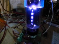
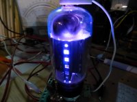
You mentioned in the first post that the tube arced when tested. Did the arc appear is white flashes or sparks inside the tube, or flashes of blue or violet light? White sparks indicate either a good vacuum, or complete air, no vacuum at all. Blue, pink or purple glow around any element or inside the plate structure indicates the presence of "gas," a contaminated vacuum, or partial air.
If the vacuum is compromised the heater will usually draw too much current. The heater and cathode will usually not reach its glowing red color, but the tube will still get warm.
Based on what was available, and common at the time that your tube is likely either a 41 or 42. Both have the same pinout, and look nearly identical, but are somewhat different. Verifying the pinout by following the wiring inside the radio can determine whether testing the tube as a 41 would cause the arcing. If the tube is wired as a 41 should be, then your tester didn't cause the sparks, the tube is probably bad, especially if a blueish glow was seen.
The tube in the picture is a worse case example. It's heater should draw 2.6 amps, but was drawing nearly 4 amps. There were sparks flying inside, but the blue glow gives away the real problem, contaminated vacuum.
Does your power supply have capability to produce 2 to 3 amps for a short time? A tube heater will draw much more than it's rated current on a cold start. If the power supply went into current limiting during this time, reducing it's output voltage, the tube might not get hot enough to reach a normal current draw. Did the tube actually draw 1.2 amps with 6.3 volts across it?
If so there are two possibilities.
The tube is a type that have not seen, and is not in my limited collection of books, or it is a common type that has some air inside it.
You mentioned in the first post that the tube arced when tested. Did the arc appear is white flashes or sparks inside the tube, or flashes of blue or violet light? White sparks indicate either a good vacuum, or complete air, no vacuum at all. Blue, pink or purple glow around any element or inside the plate structure indicates the presence of "gas," a contaminated vacuum, or partial air.
If the vacuum is compromised the heater will usually draw too much current. The heater and cathode will usually not reach its glowing red color, but the tube will still get warm.
Based on what was available, and common at the time that your tube is likely either a 41 or 42. Both have the same pinout, and look nearly identical, but are somewhat different. Verifying the pinout by following the wiring inside the radio can determine whether testing the tube as a 41 would cause the arcing. If the tube is wired as a 41 should be, then your tester didn't cause the sparks, the tube is probably bad, especially if a blueish glow was seen.
The tube in the picture is a worse case example. It's heater should draw 2.6 amps, but was drawing nearly 4 amps. There were sparks flying inside, but the blue glow gives away the real problem, contaminated vacuum.
Attachments
To try and narrow this down ,looking at the American book mentioned above it states the RMA tube type-number introduced in 1933 lists 6.3 heaters for NON- octal based tubes as-
36-37-38-39-41-42-44 this is 1930,s .
Others mentioned are-
64-64A-65-65A-67-67A-68-68A-75-75S-76-77-78-79
Previous to this US Standard companies had their own type designations.
I too am having trouble finding an output tube with this voltage & heater current of THAT era.
36-37-38-39-41-42-44 this is 1930,s .
Others mentioned are-
64-64A-65-65A-67-67A-68-68A-75-75S-76-77-78-79
Previous to this US Standard companies had their own type designations.
I too am having trouble finding an output tube with this voltage & heater current of THAT era.
Looked through an older version of WW equivalents book and to get near that current at 6.3 volts puts it into the category of small transmitting tubes but they are not UX6 but UX5/UX4 even the mighty 807 tube only consumes 0.9 amps at 6.3 volts .
Tubelab made some good suggestions there.
Tubelab made some good suggestions there.
I don't find any tube with a 6 pin base and a 1.2 amp heater in my books.
Does your power supply have capability to produce 2 to 3 amps for a short time? A tube heater will draw much more than it's rated current on a cold start. If the power supply went into current limiting during this time, reducing it's output voltage, the tube might not get hot enough to reach a normal current draw. Did the tube actually draw 1.2 amps with 6.3 volts across it?
If so there are two possibilities.
The tube is a type that have not seen, and is not in my limited collection of books, or it is a common type that has some air inside it.
You mentioned in the first post that the tube arced when tested. Did the arc appear is white flashes or sparks inside the tube, or flashes of blue or violet light? White sparks indicate either a good vacuum, or complete air, no vacuum at all. Blue, pink or purple glow around any element or inside the plate structure indicates the presence of "gas," a contaminated vacuum, or partial air.
If the vacuum is compromised the heater will usually draw too much current. The heater and cathode will usually not reach its glowing red color, but the tube will still get warm.
Based on what was available, and common at the time that your tube is likely either a 41 or 42. Both have the same pinout, and look nearly identical, but are somewhat different. Verifying the pinout by following the wiring inside the radio can determine whether testing the tube as a 41 would cause the arcing. If the tube is wired as a 41 should be, then your tester didn't cause the sparks, the tube is probably bad, especially if a blueish glow was seen.
The tube in the picture is a worse case example. It's heater should draw 2.6 amps, but was drawing nearly 4 amps. There were sparks flying inside, but the blue glow gives away the real problem, contaminated vacuum.
I just checked the power supply and I had its current set to his highest limit which is 3 amps.
The arcing I get on the tester happens when I switch it to test mode when the HT is applied. Im also getting some arcs on the rotary switch on the tester itself when i looked underneath. I suspect its shorting since the overload light comes on my tester.
The arcing looks nothing as spectacular as your photos, it was literally just a small flash inside the bottom of the tube where the wires come up through the glass. Looked like small sparks between the wires rather than a flashover that does not go away.
Anyway, I suspect the tester is configured for the wrong type if thats the case.
My main concern though is i possibly damaged the heater as I first tested it assuming it was a 41 which has a much higher heater voltage than a 42, it glowed pretty bright so i turned it off immediately. Could that affect the current draw if its damaged? It appears that the full heater was working however.
If the heater isn't blown but still lights up large over current causing it to glow excessively bright can and does severely shorten its life/emission as well as the heat expansion in a lot of cases causes a heater/cathode short circuit .
Yes a 41 only has a third of the heater current than a 42, the range of numbered UX6 tubes or UX5/UX4 I listed above all work from 6.3 heaters and that includes the 41.
Be aware Cosser (UK) an UK valve manufacturer had "type 41/42" but the bases were different --Br range and they all had letters after the type number and had 4 volt heaters .
In a non faulty valve testing with the wrong settings causes arcing my AVO VCM MK4 immediately cuts out the power automatically-- trying plugging a 5Y3GT rectifier into a 5Z4G base and just watch the sparks .
The facts are -
you tested the heater voltage --its 6.3 volts -
all UX6 based valves that operate at 6.3 volts I have listed above .
If the heater isn't blown but still lights up large over current causing it to glow excessively bright can and does severely shorten its life/emission as well as the heat expansion in a lot of cases causes a heater/cathode short circuit .
Yes a 41 only has a third of the heater current than a 42, the range of numbered UX6 tubes or UX5/UX4 I listed above all work from 6.3 heaters and that includes the 41.
Be aware Cosser (UK) an UK valve manufacturer had "type 41/42" but the bases were different --Br range and they all had letters after the type number and had 4 volt heaters .
In a non faulty valve testing with the wrong settings causes arcing my AVO VCM MK4 immediately cuts out the power automatically-- trying plugging a 5Y3GT rectifier into a 5Z4G base and just watch the sparks .
The facts are -
you tested the heater voltage --its 6.3 volts -
all UX6 based valves that operate at 6.3 volts I have listed above .
I just realized I posted the wrong tube type. It was a 43 I originally tested it as which has a 25v heater.
I think there is a good chance there is damage to the heater, my friend said the heater was flickering on and off when he switched it on. No doubt I would have done more damage over powering the heater on my tester.
Looking at the test data for all these ux6 tubes, they are all wired the same for the tester and only difference I can see is bias voltage on the grid.
I'm definitely seeing some sort of short happening inside the tube, and as you say it's likely the cathode.
Would you say that it's a good educated guess that it's a 41?
We seem to be at a point where no absolute conclusions can be drawn.
The tube draws what appears to be too much current when fed 6.3 volts. A 41 and a 42 both operate from 6.3 volts, so either the tube is not one of these, or it is bad.
The tube misbehaves when tested as a 41, so again it is either not a 41, or it is bad.
At this point more information is needed. If I was working on this I would have already looked into the only place that can provide more information, the radio itself.
The pictures posted here are not sufficient to find similar designs that may provide clues. I can't tell from the photos if the radio is a reflex, TRF, or superhet. How many tubes does it have, and what are the known numbers, or what is written on the chassis next to the socket. How
We know that there is a 6B7 tube, and a 6U5, so the radio has a 6.3 volt source, which usually feeds all the tubes. Verify that the mystery tube is receiving 6.3 volts. It it wired in parallel with the others?
If so it may be necessary to follow each pin on the mystery tube to see if it is connected up like a 41 or 42, or uses a different pin scheme. IE, does the wire from the OPT on the speaker go to pin 2?
I see that you posted new information while I was typing. You tested the mystery tube as a type 43? If so this could have damaged it's heater, especially if you saw sparks inside.
Try testing it as a 41 or 42. Both of these run from 6.3 volts, have the same pinout, and are similar enough to not fry if you test one as the other.
Try testing it as a 41 or 42. Both of these run from 6.3 volts, have the same pinout, and are similar enough to not fry if you test one as the other.
I see that you posted new information while I was typing. You tested the mystery tube as a type 43? If so this could have damaged it's heater, especially if you saw sparks inside.
Try testing it as a 41 or 42. Both of these run from 6.3 volts, have the same pinout, and are similar enough to not fry if you test one as the other.
Yes I thought 43 was the best guess at the time until found out about types 41 and 42, which I have already since tried testing it as.
I was getting the sparks when testing as a 41 or 42 and applying the HT, not as a 43 which I turned off as soon as I saw the heater glowing bright.
There was another type that I tested but can't remember it off the top of my head, but pinouts on it was identical to the 41.
I dont have the radio on me, as it's still at my friends. I just pulled out the suspect tube to test.
I can confirm it has 5 tubes plus the magic eye.
I will likely end up bringing the set over when I make some space for it on my workbench. It will likely need a recap too.
If you had told me its a 5 valve + magic eye I could have saved many hours of trouble , after looking through long lists of radios by the company I came across that configuration but discounted it as only now have you presented those facts .
I am trying to work out if I am able to spend so much time rediscovering this circuit as it took several browsers + search engines to narrow it down.
I am trying to work out if I am able to spend so much time rediscovering this circuit as it took several browsers + search engines to narrow it down.
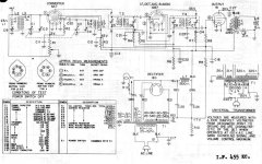
A quick look at the tuning capacitor would tell if it's a TRF / reflex or a superhet, but being 5 tubes plus eye, probably makes it a superhet, and likely similar to the circuit using 6 volt tubes shown in post #16.
A superhet should have two of the metal cans like seen on the left side of the chassis. These are the IF transformers, and one should not turn the alignment screws on the top of them.
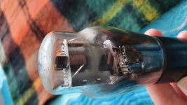
The type 41 is the predecessor to the 6K6. The 42 is the forerunner of the 6F6. Both tubes are similar, and I have swapped the 6K6 and 6F6 in a out of the same circuit along with a 6V6. They all work, but require different biasing. If the radio is cathode biased (most likely) either a 41 or a 42 should get sound for testing. The pictures posted look more like a 6K6 (more oval plate) than a 6F6 (more rounded plate). That would make it a 41.
If the radio was designed for a 41 one should not use a 42 for other than short tests. The extra heater current draw is not good for a nearly 90 year old transformer.
A superhet should have two of the metal cans like seen on the left side of the chassis. These are the IF transformers, and one should not turn the alignment screws on the top of them.
The type 41 is the predecessor to the 6K6. The 42 is the forerunner of the 6F6. Both tubes are similar, and I have swapped the 6K6 and 6F6 in a out of the same circuit along with a 6V6. They all work, but require different biasing. If the radio is cathode biased (most likely) either a 41 or a 42 should get sound for testing. The pictures posted look more like a 6K6 (more oval plate) than a 6F6 (more rounded plate). That would make it a 41.
If the radio was designed for a 41 one should not use a 42 for other than short tests. The extra heater current draw is not good for a nearly 90 year old transformer.
[
Yeah look, im sorry. I didnt know myself until I went back to take another look at it.
I honestly didnt realise the significance of this at the time.
I will be able to work on it next week hopefully and find more info.
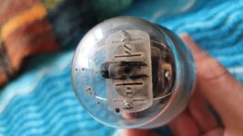
There is an ARTS&P label on the back, but its badly worn and hard to read.
I guess I can figure out what type of tube it is going by whatever cathode resistor is attached?
Anyway, here is another photo of the top of the tube.
If you had told me its a 5 valve + magic eye I could have saved many hours of trouble , after looking through long lists of radios by the company I came across that configuration but discounted it as only now have you presented those facts .
I am trying to work out if I am able to spend so much time rediscovering this circuit as it took several browsers + search engines to narrow it down.
Yeah look, im sorry. I didnt know myself until I went back to take another look at it.
I honestly didnt realise the significance of this at the time.
I will be able to work on it next week hopefully and find more info.
I think your right, the link on post #16 could be the very same design.A quick look at the tuning capacitor would tell if it's a TRF / reflex or a superhet, but being 5 tubes plus eye, probably makes it a superhet, and likely similar to the circuit using 6 volt tubes shown in post #16.
A superhet should have two of the metal cans like seen on the left side of the chassis. These are the IF transformers, and one should not turn the alignment screws on the top of them.
The type 41 is the predecessor to the 6K6. The 42 is the forerunner of the 6F6. Both tubes are similar, and I have swapped the 6K6 and 6F6 in a out of the same circuit along with a 6V6. They all work, but require different biasing. If the radio is cathode biased (most likely) either a 41 or a 42 should get sound for testing. The pictures posted look more like a 6K6 (more oval plate) than a 6F6 (more rounded plate). That would make it a 41.
If the radio was designed for a 41 one should not use a 42 for other than short tests. The extra heater current draw is not good for a nearly 90 year old transformer.
There is an ARTS&P label on the back, but its badly worn and hard to read.
I guess I can figure out what type of tube it is going by whatever cathode resistor is attached?
Anyway, here is another photo of the top of the tube.
Attachments
Last edited:
If the radio is cathode biased (most likely) either a 41 or a 42 should get sound for testing.
Some of those radios used 'back bias', developed across the drop in the loudspeaker field coil, which was in the negative return lead to the PT.
If the cathode terminal on the output tube is soldered to the chassis then the circuit is back biased.🙂
Some of those radios used 'back bias', developed across the drop in the loudspeaker field coil, which was in the negative return lead to the PT.
If the cathode terminal on the output tube is soldered to the chassis then the circuit is back biased.🙂
I'm in NZ. PM me if you want it tested. I have spare 41/41E/42 here but I will have to check if they are OK.
The one you have certainly looks identical to my Philco 41
The one you have certainly looks identical to my Philco 41
- Home
- Amplifiers
- Tubes / Valves
- Is this a 41 valve?