
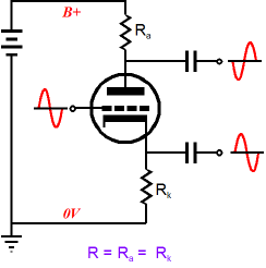
Can someone explain why the anode output is out of phase (inverted)?
Similarly, why the cathode output is in phase?
As the grid voltage increases, the anode to cathode electron flow increases, increasing the current flow and the voltage across Ra increases.
As the grid voltage decreases, the electron flow decreases and so does the voltage across Ra.
The cathode follows the grid voltage.
It is an invertor.
If one holds the cathode at a set voltage, the valve then has voltage gain, similar to a semiconductor ... almost.
As the grid voltage decreases, the electron flow decreases and so does the voltage across Ra.
The cathode follows the grid voltage.
It is an invertor.
If one holds the cathode at a set voltage, the valve then has voltage gain, similar to a semiconductor ... almost.
Last edited:
As the voltage on the grid rises the valve begins to conduct more heavily. If it conducts more heavily then the voltage on the anode falls. You see that as a phase inversion on an AC signal.
The cathode voltage will rise as the valve conducts more. The signal here is in phase. Voltage on the grid goes up, voltage on the cathode goes up.
The cathode voltage will rise as the valve conducts more. The signal here is in phase. Voltage on the grid goes up, voltage on the cathode goes up.
If you put 0V and -15V what happens to the current? Then what happens to the voltage drop across the three resistances in series? (Ranode, valve and Rcathode)?
Replace the tube with a variable resistor and then do some measurements, even then it is out of phase...
Thanks for the reply.
I understand that as grid voltage increases, more electrons will be attracted to anode, so the current through the tube will increase, and the increasing current will increase the voltage across Ra. But why is it inverted? It seems to me that they move in the same direction, so they should be in phase?
I understand that as grid voltage increases, more electrons will be attracted to anode, so the current through the tube will increase, and the increasing current will increase the voltage across Ra. But why is it inverted? It seems to me that they move in the same direction, so they should be in phase?
You are over thinking it.
Just think of the valve as a variable resistance between A and K, the resistance of which depends on the grid to cathode voltage and then look at the voltages at the valve nodes as per ohms law.
If the grid-cathode voltage goes up the 'resistance' of the valve goes down and vice versa.
Just think of the valve as a variable resistance between A and K, the resistance of which depends on the grid to cathode voltage and then look at the voltages at the valve nodes as per ohms law.
If the grid-cathode voltage goes up the 'resistance' of the valve goes down and vice versa.
Replace the tube.... use a resistor instead... see the same behavior... it has nothing to do with the tube at all. Just 3 resistors (as this is how the tube behaves, a "non" linear resistor).
For the cathode resistor Rk and cathode output, increasing grid voltage will lead to increasing current, which leads to increasing voltage across the Rk , so output from there will be in phase with input signal. This part seems okay to me.
I just couldn't figure out why the anode output is inverted.
I just couldn't figure out why the anode output is inverted.
You can even make it more simple. A switch instead of the tube.... short circuit and the voltage is devided by the 2 resistors right? Open the switch and each resistor is either ground or B+.... So one is high and the other is low.... out of phase...
Plate current is in phase with grid voltage.
But then that current generate the voltage drop across the plate load, and that drop "pushes off" the output from the B+ (Va in your picture), not from the ground. That's why the voltage output is inverted.
But then that current generate the voltage drop across the plate load, and that drop "pushes off" the output from the B+ (Va in your picture), not from the ground. That's why the voltage output is inverted.
That's right. B+ is grounded for AC, so as the current increases through the anode resistor and the Voltage across it increases, its lower end moves down.
Similarly, with the valve and the anode resistor being the two main Voltage drops, as you increase grid Voltage, the valve opens and its instantaneous resistance drops. So does the Voltage seen across it.
Similarly, with the valve and the anode resistor being the two main Voltage drops, as you increase grid Voltage, the valve opens and its instantaneous resistance drops. So does the Voltage seen across it.
I once thought it might be the case. Anode voltage = (B+) - (voltage drop across Ra). But if we use this formula, the anode voltage will not agree with the formula below.
Assuming the cathode resistor is bypassed by a capacitor, then we have Vout = - u * Vin, here the anode voltage Vout will not agree with the anode voltage formula above.
Assuming the cathode resistor is bypassed by a capacitor, then we have Vout = - u * Vin, here the anode voltage Vout will not agree with the anode voltage formula above.
Don't think with formulas, think with processes. Formulas don't determine what's hapenning, they only describe it (and your second formula is incorrect BTW).
Stand in the doorway. Raise your hands and put your palms on the doorway's top beam. Relax your feet a bit.
Then start to push on that top beam with your hands.
As the applied power ("input signal") goes up, your head ("plate") goes down.
That's it.
Stand in the doorway. Raise your hands and put your palms on the doorway's top beam. Relax your feet a bit.
Then start to push on that top beam with your hands.
As the applied power ("input signal") goes up, your head ("plate") goes down.
That's it.
Let´s see if you get this way, with some arbitrary but realistic numbers:
1) suppose you have a tube with Rk=1k ; Ra=100k, idle current = 1 mA , +V supply=300Vdc.
Does it sound reasonable to you?
2) also suppose (it is a simplification) the Vk and Vg difference stays the same.
3) now let´s calculate voltages present :
* Vk is 1V (1mA*1k) more positive than Vg but more significant, more positive than ground.
* Va is 100V "less positive/more negative" (same thing) than +V so it is :
Va= 300V - (1mA * 100k)= 300V-100V= 200V
Specially note that it is more negative than +V
Do we agree?
4) now apply +0.1V to grid. (input signal). It is positive going, we can call it "positive phase"
Let´s calculate new voltages, still assuming difference between Vg and Vk remains constant (Vg stays 1V more negative than Vk).
* Vk now will be 1.1V
More positive than before, following a more positive Vg, so it is in phase with input signal.
And also same voltage increase as in Vg
* Current will be higher: 1.1V across 1k means now we have 1.1mA
* so Anode current will be higher, also 1.1mA
Why?: because cathode resistor, triode and anode resistor are in series, and current has nowhere else to go, so it´s exact same on all 3
* now let´s calculate Anode voltage:
Va= 300V - (1.1mA * 100k) = 300V - 110V = 190V
Notice this, which confuses many: although Anode is still positive (it always is) but its voltage is less positive than before , or as I mentioned above: "more negative" than before, so SIGNAL is negative (it´s going "downwards")
You can now clearly see that Output Signal phase is now negative so it is inverted compared to Input Signal.
Please read this until it "clicks" and then you´ll never forget it.
A similar mechanism explains Transistor (Bipolar or FET or MosFet) signal/phase inversion and going a little further, Op Amp phase inversion.
PS: now that we are at it, let´s also explain Gain:
Vg=Vk variation: 0.1V (Input Signal)
Va variation: -10V (Output Signal)
Gain: Output Signal/Input Signal=-10V/0.1V=-100X
Notice the minus sign applied to gain: out of lazyness we seldom write it, some say "it´s AC anyway, who cares?" but as you see it IS important, not making it clear and visible CAN lead to confusion.
Last edited:
I once thought it might be the case. Anode voltage = (B+) - (voltage drop across Ra). But if we use this formula, the anode voltage will not agree with the formula below.
Assuming the cathode resistor is bypassed by a capacitor, then we have Vout = - u * Vin, here the anode voltage Vout will not agree with the anode voltage formula above.
Total Resistance = Ranode + Rvalve + Rcathode
V=IR still works..
Someone said once (IIRC it may have been YouTube) that the valve essentially is floating between the B+ and ground (or B-). As the grid changes in relative to the cathode it lets more current through thus as you get closer to zero (ie max current) the more current flows through the cathode, so V=IR, V= Imax*Rc, thus as the voltage on the grid goes up (to zero) then V=I (ignore R as we can assume a constant if we like for simplicity) for the cathode, so the voltage increases. At the same time the valve decreases in resistance. Et Voila - you have voltage in phase.
A simpler way is if we have 10R for each with the valve having a max of 10R too... it becomes a potential divider.
Idealistically Rtotal(zero grid) = Ranode + (zero) + Rcathode
= 10 + 10 which means both anode and cathode see the centre point (there's no resistance to separate them). This is because at zero grid the ideal valve has no resistance.
Idealistically, Rtotal(max grid -) = Ranode + Rmaxvalve + Rcathode
= 10 + 10 + 10 which means the anode sees 1/3 from the B+ and the cathode sees 2/3 from the B+ (or 1/3 from the ground etc). They are separated by the resistance of the valve.
A wave on the grid that goes 0V -gmax 0V -gmax 0V -gmax now appears as:
At the anode = 1/2 1/3 1/2 1/3 1/2 1/3
At the cathode= 1/2 3/2 1/2 2/3 1/2 2/3
So if you draw that it's 180 degrees out of phase.
Now you can use V=IR with current etc to work this all out, but it's probably easier to think of it in resistance as you can think of the voltage dividing. If you do want to look at current, then think of everything floating, held in voltage position by the current and the resistance.. so change current using the grid.. the same happens.
Last edited:
Stand in the doorway. Raise your hands and put your palms on the doorway's top beam. Relax your feet a bit. Then start to push on that top beam with your hands. As the applied power ("input signal") goes up, your head ("plate") goes down.
That's it.
That's a great analogy! I will use that to explain it to my non-technical friends! Thank you!
Last edited:
I think the cathodyne/concertina/split-load circuit, employed in countless designs, is a good way to illustrate the concept and the voltage behavior of an amplifying tube. If we alter the grid voltage to go up, the cathode voltage goes up too (in phase). Consequently, the plate voltage goes down (out of phase).
I try not to overthink it as I am not good with math or formula. Based on observing the dynamic behavior of the tube in the process, it correlates with the concept.
I try not to overthink it as I am not good with math or formula. Based on observing the dynamic behavior of the tube in the process, it correlates with the concept.
- Home
- Amplifiers
- Tubes / Valves
- Can someone explain why the anode output is out of phase?