Maybe not the right place here on an audio forum but in "Everything Else" we can post other things .
I've been looking for a way to drive RGB LED's so that with like up/down buttons I can fluently change the colours.
Looking at the IC's on Mouser or Texas Inst sites , I can't see the trees through the forest. So many LED driver IC's but not what I am looking for.
Closest I've come to designing it myself is an up/down counter that drives the addresses of an EPROM , and its output drives the PWM of the 3 LED colours.
Problem with this is progamming the EPROM.
Even with 5 bit resolution/LED , that's near 100.000 adresses of a 1Mbit EPROM ... by hand .
There must be an easier way but without an uP using only custom IC's with logic and EPROMs.
How does Philips Hue do it ? How would you do it ?
I think you'll end up using a microcontroller type board such as arduino, Rpi, beaglebone, Teensy so you won't have to re-invent the wheel. There's good information about neopixels from Adafruit , they also have a neopixel-uberguide and a github repository for the controller code.
Some rgb led's like the neopixels are based on the WS2812, WS2811 and SK6812 controllers which have strict timing requirements, but more recent types such as the Adafruit Dotstars use a 2 wire spi communication method which don't have any specific timing requirements.
Some rgb led's like the neopixels are based on the WS2812, WS2811 and SK6812 controllers which have strict timing requirements, but more recent types such as the Adafruit Dotstars use a 2 wire spi communication method which don't have any specific timing requirements.
ESP32 is very cheap, easy to use, and it has very high resolution PWM with dithering, which is nice for dimming to low intensity without steps. Plus it has wifi.
Thanks , but microcontrollers is just what I try to avoid.
No need for single addressable LED's , just changing them all at once with the same colour.
No need for single addressable LED's , just changing them all at once with the same colour.
You can do it digitally with 3 independent PWM generators :
With a clock, one up/down counter, one ramp generator counter, one digital comparator it’s easy to do a 4 or 8 bit PWM generator where duty cycle depend on two up/down buttons.
But led brightness is a logarithmic function of Led mean current, that mean you have to design an antilog command chain: implement an antilog function between your expected brightness value (set by the button) and the duty cycle of the PWM generator. You need an EEPROM as an antilog look up table between your up/down counter and the digital comparator.
Maybe it’s simpler to do it with analog way: with some class D amp driver or switching PSU (such LM3524) chip and an opamp+diode as antilog converter.
I don’t know about Philips, but I doubt they didn’t use an Uc to manage the thing.
This sound very 80's, even 90's project: LM3524, 74191, 7485 or 74688 chips are not very common today. But it could be fun !
Today the easiest way is certainly using neopixel WS2812, Arduino and the Adafruit neopixel driver: it works flawlessly. Neopixel are far from easy to drive.
I already made a PWM with up/down counter 40193 and 74HC85 for controling white LED's , but even doing this for the 3 colours , I have to mix the colours myself and that is not what I want. I need automatic mixing of the 3 basic colours so that with only 1 set of up/down buttons it goes from red to blue with all the colours in between.
Yes it sounds like an 80's or 90's project , which suits me fine because I am still in the 80's 🙂.
Yes it sounds like an 80's or 90's project , which suits me fine because I am still in the 80's 🙂.
I have a cheap computer mouse which has a RGB LED changing in a limited amount of colours , but it won't work with just the 5V from the USB .
So it can be done simple although it smoothly changes into about 8 colours .
I'm not that concerned with the logarithmic brightness of the LED .
So it can be done simple although it smoothly changes into about 8 colours .
I'm not that concerned with the logarithmic brightness of the LED .
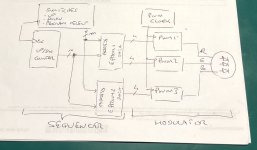
I think it is clearer now: with two button (up/down) you want to cycle through a kind of predetermined color wheel.
This is a kind of sequencer going through a program through steps, each step Is a combination of three colours R, G and B. The program move to next/previous step with up/down button.
You need a counter a one or more memory to handle the program (color cycling), but you also need three of your already made PWM modulator. This is very much like some Christmas tree decoration.
The main question will be color depth: how many total color do you want? 64 (4 colors per primary one), 2048 (16 colors per primary one, or even 16M (256 colors per primary).
If you go 2048, you’ll need 12bits wide EPROM, so 2 chips; if you go 64, a single chip EPROM will be sufficient. If you go 16M, 3 EPROM will be necessary. (Assuming EPROM chip is 8 bits data wide)
The attached block diagram could be an implementation with 16 colors per primary one.
The size of your program will be 2^n; and depending on the size of the EPROM you could have 2^m programs. Each PWM block. This is your choice. Which type of EPROM do you plan to use?
Attachments
If you're willing to give up the up/down buttons and replace them with continuous adjustments (pots), you could use three 555 timer ICs to create three PWM generators to drive the LEDs. There's a PWM circuit in TI's 555 data sheet.
And actually now that I think about it: I wonder if you can replace the pot in the 555 PWM circuit with a digital pot. Possibly even one that supports up/down input. If a digital pot doesn't accept up/down input, perhaps you can find one with a parallel interface so you can drive it with a 7400 or 4000 series logic IC up/down counter.
Another option would be to look at LED drivers for the cellphone industry. You may be able to narrow things down if you search for "fun lighting" at TI for example. I recall my colleagues at National Semiconductor (now TI) working on some of those ICs. For whatever reason the LEDs on older cellphones (pre-smartphone) were referred to as "fun lighting". I bet they require a serial input, though. But it's worth a look.
Tom
Last edited:
LM3435 is probably the kind of chip you refer to:
https://www.ti.com/lit/ds/symlink/l...03878&ref_url=https%3A%2F%2Fwww.google.com%2F
https://www.ti.com/lit/ds/symlink/l...03878&ref_url=https%3A%2F%2Fwww.google.com%2F
If you really want a old style circuit, I would try to do it this way:
- Take a CD4022 Johnson counter. Each output can source about 5mA at 12V. It is a Johnson counter, each clock pulse will put the next output pin at logic high level. This chip is (quite surprisingly) still available on most electronic suppliers.
- connect the anode of 3 diodes at the first output pin (output 0).
- connect a resistor in series with each diode. Let's call them: R0r R0g and R0b because they set the weight of the red, green and blue LED current.
- repeat for output pin 1 to 7.
- connect the other end of all 8 Rr resistors to the input of a high current op-amp configured as buffer. Or use a discrete power device, many choices are available. Do the same for the green and blue channels.
- each clock pulse will activate the next counter output, and a different color scheme will be selected. BOM: 1 CD4022 counter, 1 quad op-amp, 24 diodes, 24 resistors.
It may or may not work, try at your peril.
Last edited:
I think it is clearer now: with two button (up/down) you want to cycle through a kind of predetermined color wheel.
This is a kind of sequencer going through a program through steps, each step Is a combination of three colours R, G and B. The program move to next/previous step with up/down button.
Yes that's it and your diagram is spot on.
Like I said before : 5 bit resolution /LED is about 32.768 /LED x 3 (RGB) =
98.304 colours/shades , this is more than enough . The 3 other bits of the 8 bit
EPROM is to toggle between the 3 LED's.
It could be done at 4 bit res : 4096 colours x 3 = 12,288 adresses but since LED's
are logarithmic , the steps will not be fluent.
The problem with this is programming the EPROM . I have to do this by hand with
a device I made late 80's and is in another country than me , I'm an expat.
No need for a 12 bit wide EPROM though.
I've done 27Cxxx EPROMS before , like going from a 8 digit multiplexed output to
a 2 x 24 character dot matrix LCD with much more information on it .
And actually now that I think about it: I wonder if you can replace the pot in the 555 PWM circuit with a digital pot. Possibly even one that supports up/down input. If a digital pot doesn't accept up/down input, perhaps you can find one with a parallel interface so you can drive it with a 7400 or 4000 series logic IC up/down counter.
Then you need to continually adjust the 3 pot's to search for a colour , impractical.
Or write down the numbers on the digital pot.
Well I wouldn't have searched for "fun lighting" , thanks. 🙂
A look there and so far driven by SMBUS/I2C , so that's not for me , but I'll keep looking there.
LM3435 is probably the kind of chip you refer to:
https://www.ti.com/lit/ds/symlink/l...03878&ref_url=https%3A%2F%2Fwww.google.com%2F
Well the title already says it :
RGB LED driver with I2C controle interface . It needs commands from another source.
Driving the RGB's in PWM is not a problem , sending the "commands" to make the different colours is.
If you really want a old style circuit
Old style , best style ! 🙂
With the 4022 that would get me 8 different colours ? Not that much , if I understand it right and it will be very step like , not fluent. 74HC4017 in 10 steps , or a 4 to 16 decoder or more.
Having only a limited amount of colours is not much of a problem to make . I guess this is done by simple RGB lights on like computer fans or christmas lights or on a computer mouse like mine.
But limiting the steps could be a simpler way to go.
Are you sure you understand how cheap and simple addressable LEDs are? Only 3 or 4 wires drives the entire array (+V, -V, data). You can roll your own controller with an Arduino etc. or you can buy a ready made controller. The one I bought controls the LEDs with an app on your phone or PC via Bluetooth. RGB LEDs are hardly DIY, more like a consumer product. Go to Amazon and search "RGB controller". You don't have to build anything.
Last edited:
Yes that's it and your diagram is spot on.
Like I said before : 5 bit resolution /LED is about 32.768 /LED x 3 (RGB) =
98.304 colours/shades , this is more than enough . The 3 other bits of the 8 bit
EPROM is to toggle between the 3 LED's.
It could be done at 4 bit res : 4096 colours x 3 = 12,288 adresses but since LED's
are logarithmic , the steps will not be fluent.
The problem with this is programming the EPROM . I have to do this by hand with
a device I made late 80's and is in another country than me , I'm an expat.
No need for a 12 bit wide EPROM though.
I've done 27Cxxx EPROMS before , like going from a 8 digit multiplexed output to
a 2 x 24 character dot matrix LCD with much more information on it .
As this is an 80s project I was thinking to 2716 EEPROM 😉…
This programmer is cheap and well known, at least here in DIYA or EEVBlog :
Programmeur universel USB 13000 EPROM FLASH BIOS 6, 1 kit 2.0 ICs TL866II adaptateur PLCC IC TL866A haute vitesse 100% original | AliExpress
If you don’t want to buy one, I’m sure you’ll find someone here or on EEVBlog keen to program you some EEPROM.
Excel can be used to compute the R,G and B sequences then merge them in order to produce the file to program with the programmer. No need to go VBA programming, there’s a lot to do with XL functions.
With 4 or even 5 bits color depth per primary color, you’ll need two EEPROM in order to provide the 12 or 15 bits to the 3 PWM modulators at each program step. Steps are sample, animation speed is sampling frequency, this where your project get close of digital audio stuff…
I’m not sure to get your calculations; some comments :
5 bits / per primary color (Led) is 32 shades (2^5); 4 bits is 16.
If EEPROM output drive PWM modulators and you use lets’ says 4 bits per Led, you should have EPROM1 Data0 to 3 out for Red, the EPROM1 Data4 to7 out for Green and EPROM2 Data0 to 3 for Blue.
There’s no relationship between the number of address and the number of total shade you want to use. The number of address is the number of step in your program. If you want very smooth transition, you’ll have a lot of steps between color a and color b. If you just want toggle between 8 or 16 total colors, you need 8 or 16 steps.
If you want smooth transition, you can decide that a transition is an arbitrary number of steps (lets say 64) and each time you press a button the sequencer count (up or down) 64 steps. You don’t have to press the button 64 times…
Chris
Last edited:
Are you sure you understand how cheap and simple addressable LEDs are? Only 3 or 4 wires drives the entire array (+V, -V, data). You can roll your own controller with an Arduino etc. or you can buy a ready made controller. The one I bought controls the LEDs with an app on your phone or PC via Bluetooth. RGB LEDs are hardly DIY, more like a consumer product. Go to Amazon and search "RGB controller". You don't have to build anything.
I am older and self taught with much help from books and Elektor , back in the day when they had decent projects (so a very long time ago) 🙁.
Everything with programmable controlers or proccesors like arduino , raspberry pi , and all the controllers elektor uses is way above my head.
Single addressable LED's are not needed , I don't need effects just all LED's changing the same colour. They even have it on airplanes where the lighting colours change to wake you up , althrough just a few colours changing fluently.
Why are RGB's not DIY ?
Very few things these days are still worth while to DIY . You don't need to make a clock or temperature meter with logic gates like we did in de 80's while you buy a nice product with a big custom LCD for 10 $/€ that can do even more.
Audio projects and I think LED's are worth while. I determine which LED's , how many and in what kind of package .
And I don't have a smartphone or blue tooth to control them . IR remote would do just fine , if only Philips wouldn't have killed SAA3049.🙁
As this is an 80s project I was thinking to 2716 EEPROM 😉…
Haha , funny Chris !
I programmed a 27C64 and a 27C256 for that project in 1990. (AMD's I think) And no these are EPROMS with the little UV window , no E-EPROM's.
They still worked in 2017 ... I haven't been back "home" since then and some addresses may be corrupted by now , but I copied both eproms around 2002-2003 .
The programmer you link , needs a computer to connect to and I have no clue how to write the data on the computer to go in the EPROM.
No my calculations are ok.
You use A0 and A1 of the EPROM address to toggle between the 3 LED's and the rest of the addresses driven by the up/down counter to set the colour , so the 8 bit data outputs are enough to drive 3 LED's in max 6 bit res + 2 for selecting which LED from the 3 , RGB. ( you could drive 8 leds in 5 bit res or 16 leds in 4 bit res).
I've made many projects with 2708, 2716 and 32 in early 80s. First ones (when IBM PC didn't exist nor Excel) imply hand coding EEPROM data then programming them with a Toyo PECKER (EPROM Programmer PKW-5000 pecker-I TOYO TELESONICS). This was very DIY !
TL866 is shipped with a PC software. There are many videos about it on YouTube.
Ex for an early version : EEVblog #411 - MiniPro TL866 Universal Programmer Review - YouTube
I’ve no experience with it, but I’m pretty sure you can load a file in the software to program it. File can be .hex, .bin, elf or even raw data written in a text file.
Could you post a schematic, your description doesn’t fit to my diagram (post #8).
Do you use a multiplexed scheme ? Because from what I read from your explanation, at a specific time there’s an address on the EPROM, then EPROM output 8 bits of data with 5 or 6 bits for brightness and 2 or 3 to select the PWM modulator. So at a time you specify brightness for only one color (one PWM modulator), but you have tree color to manage. Do you cycle across three PW modulators in order to they receive one at a time the brightness value of their corresponding color ?
Last edited:
- Home
- General Interest
- Everything Else
- Driving RGB LED's