Has nobody asked what the original opamps were, what the replacements are and whether those trimmers connect to the offset null pins.
Also beware that not all offset null circuits are the same and some opamps have very different null arrangements and recommended trimmer values. Some use pins 1 and 5 and other 1 and 8. Also some opamps need the trimmer referenced to the + rail and others to the - rail.
So you need to check.
Also beware that not all offset null circuits are the same and some opamps have very different null arrangements and recommended trimmer values. Some use pins 1 and 5 and other 1 and 8. Also some opamps need the trimmer referenced to the + rail and others to the - rail.
So you need to check.
Original ones are Signetics NE5534N and replaced them Burson v6 Vivid. At tteir website they say these are direct replacements for ne5534. Maybe I will just leave like this since it works and sounds fine and continue on speakers. Thank you
1&8 are the offset adjustments I can understand why you like the Burson,s as opposed to the NE5534,s but if you are happy as it is no point in doing any more .
As Mooly has questioned whether they are offset trimpots its easy enough to use your ohmeter setting to make sure the trimmer connections go to 1&8 on each one first but if I am right you adjust the output on the audio chip to to zero or near it .
This will be pin 6 which is the output -- I am talking here about the connections for the original chip but if the Burson,s are a pin for pin match then they should be identical.
This will be pin 6 which is the output -- I am talking here about the connections for the original chip but if the Burson,s are a pin for pin match then they should be identical.
Last edited:
Attention, the four pots visible in picture of post 1 are no "offset" trims.
Appears that the circuitry near the pots is a discrete regulator dual polarity power supply,
so those pots would then be regulator voltage adjust pots (perhaps for 15VDC).
This unit is built as dual mono, so one pot per channel, per polarity. A total of four.
Notice the large power supply capacitor array located next to this regulator circuitry.
And this unit is only a line stage, so there are no phono preamp circuits in it.
Last edited:
Okay and at caps voltage is higher than these capacitors are rated for. 37.7v one polarity and other 36.6v.
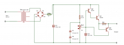
We don't know anything for certain, but the four pots appear to be associated with
four discrete DC voltage regulator circuits. Some such circuits do use pots to precisely set
their output DC voltages. Here is just one example of such a circuit, but there are many others.
four discrete DC voltage regulator circuits. Some such circuits do use pots to precisely set
their output DC voltages. Here is just one example of such a circuit, but there are many others.
Attachments
Last edited:
Original ones are Signetics NE5534N and replaced them Burson v6 Vivid. At tteir website they say these are direct replacements for ne5534. Maybe I will just leave like this since it works and sounds fine and continue on speakers. Thank you
The Burson is an unknown as far as whether the offset pins are even used... I suspect they are not.
Also Burson claim a maximum supply voltage of 33v (-/+16.5v) while an NE5534 is specified up to 40v (-/+20v) and with an absolute maximum even higher than that (-/+22v). So in no way are they a direct replacement for all applications.
You also need to investigate your concern over the caps you mention having more than their marked voltage across them... and you have to measure across unless you are sure they are ground referenced. Those voltages sound like unregulated ones. If so check that the mains voltage rating of the preamp (220v, 230v, 240v etc) matches your own supply at home. Also make sure your supply is what it is supposed to be and not to high. And be careful if you measure AC mains voltage.
Looking as best I can at the picture in post #1 and I have doubts whether the trimmers are connected to the offset pins.
Some basic checks you can do.
1/ You do need to measure the voltage on pins 4 and 7 of the Bursons. If there is more than 33 volt in total then you are running them outside their ratings.
2/ You could accurately record the voltages you measure above and using those as a reference carefully adjust one trimmer and see if one of those rails alters. If it does we know then that the trimmer adjusts the PSU.
I'm just posting as a normal member here 🙂 so say what you want 😉
Only when the is on is it official 😀
Only when the
is on is it official 😀Hi. Their pins 4&7 showing around 23.50v on each op amp and pins 4&6 is around 24 50v. Turning trim pots voltage at transistors Base, Emitter Increasing or decreasing. Increasing that voltage, temperature of transistors rises too. What mV should i set all transistors for optimal? Now It's 500mV.The Burson is an unknown as far as whether the offset pins are even used... I suspect they are not.
Also Burson claim a maximum supply voltage of 33v (-/+16.5v) while an NE5534 is specified up to 40v (-/+20v) and with an absolute maximum even higher than that (-/+22v). So in no way are they a direct replacement for all applications.
You also need to investigate your concern over the caps you mention having more than their marked voltage across them... and you have to measure across unless you are sure they are ground referenced. Those voltages sound like unregulated ones. If so check that the mains voltage rating of the preamp (220v, 230v, 240v etc) matches your own supply at home. Also make sure your supply is what it is supposed to be and not to high. And be careful if you measure AC mains voltage.
Looking as best I can at the picture in post #1 and I have doubts whether the trimmers are connected to the offset pins.
Some basic checks you can do.
1/ You do need to measure the voltage on pins 4 and 7 of the Bursons. If there is more than 33 volt in total then you are running them outside their ratings.
2/ You could accurately record the voltages you measure above and using those as a reference carefully adjust one trimmer and see if one of those rails alters. If it does we know then that the trimmer adjusts the PSU.
Last edited:
I'm not really following what you are measuring there 🙂
Pin 4 of the opamp is the negative supply voltage.
Pin 7 is the positive supply voltage.
If you measure from ground I would expect pin 4 to be a negative voltage and pin 7 a positive one. If you have -23.5 on pin 4 and +23.5 on pin 7 then that is a total of 47 volts which is way outside the Burson recommended limits. It is even outside of the NE5534 spec by a small margin.
I just added NE5534 back. Voltages at op amp are same adjusting that trim resistor. I will leave it alone. Thanks for help.��
Last edited:
OK 🙂
This really is a case of us needing the circuit details to advise better... without and it is all guesswork.
(we can say for sure though that if you read more than 33v with your meter lead between pins 4 and 7 (that is the total supply voltage across the chip) that the Burson devices are not going to be suitable)
Hi. Bringing back question about those trimmers anyone has an idea what voltage to set them? I accidentally burned 2 resistors because adjusting trimpots without care. I replaced resistors, but not sure what should be stock parameters.
We come back to the same problem of it being guesswork without more circuit details.
All you can do is carefully adjust them and see by measurement what changes such as a supply voltage or an offset voltage. Note all the supply voltage down and also all the offsets. Tweak the preset/s (maybe one at a time) and remeasure and see what changed.
All you can do is carefully adjust them and see by measurement what changes such as a supply voltage or an offset voltage. Note all the supply voltage down and also all the offsets. Tweak the preset/s (maybe one at a time) and remeasure and see what changed.
- Home
- Source & Line
- Analog Line Level
- Trim pots on preamplifier circuit