Anand:
Thank you for the pointers. I am attaching pictures of my powersupply. Note that I am using two Hammond transformers as I could not source the nice toroidals everyone here seems to be using. See the attached link here for pix.Facebook
Also, I checked to see that none of the MOSFETs were grounded . . .check.
Voltage at Z1 = 4.45V
Voltage at Z2 = 5.9V
But the transistors for Q3 and Q4 are both LSK170s!! I think I found the problem. . . . and this is for the channel that could not get the offset to 0.
If you can use some other non social media based site to upload the pics it would be more accessible to most folks here. I have got FB but I can't see your pics.
Best,
Anand.
Best,
Anand.
Trouble shooting F6 bias/offset . . . powersupply pix first
Anand:
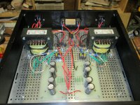
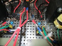
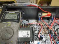
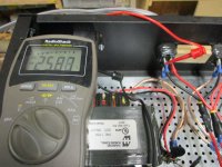
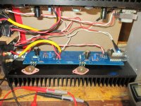
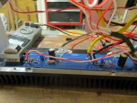
Okay . . . perhaps this will work better. I could not source the nice toroidal transformers that other builders have been using, so I opted for two Hammond trannys. The first picture shows the entire powersupply in its own separate chassis. On the left we have the side that produces +26 VDC and on the right side the circuit that produces -26 VDC. Each side has its own thermistor/cap elements to deal with the soft start on the primary side of the transformer. Pix are shown. Also shown is the voltage on the output connections, with 25.88 VDC on the right side of the connector, and -25.88 VDC on the left side of the connector, for a total voltage difference of 51.6 VDC.
At least ONE of my problems is that the JFETS I used were ONLY the 2SK170 types. I ordered a new matched set of 2SK170/2SJ74 quads for the store. As soon as I get those in they will be installed, and we will see where we go from there.
I so appreciate your help so far!!
rolf
Anand:
Okay . . . perhaps this will work better. I could not source the nice toroidal transformers that other builders have been using, so I opted for two Hammond trannys. The first picture shows the entire powersupply in its own separate chassis. On the left we have the side that produces +26 VDC and on the right side the circuit that produces -26 VDC. Each side has its own thermistor/cap elements to deal with the soft start on the primary side of the transformer. Pix are shown. Also shown is the voltage on the output connections, with 25.88 VDC on the right side of the connector, and -25.88 VDC on the left side of the connector, for a total voltage difference of 51.6 VDC.
At least ONE of my problems is that the JFETS I used were ONLY the 2SK170 types. I ordered a new matched set of 2SK170/2SJ74 quads for the store. As soon as I get those in they will be installed, and we will see where we go from there.
I so appreciate your help so far!!
rolf
Attachments

Rolf,
I always like to see different implementations of Pass builds. Nice work. The toroid transformers most use here are from Antek. Here is an example for your future builds:
AS-3218 - 300VA 18V Transformer - AnTek Products Corp
Your power supply DC output voltages look great. The chassis ground appears visible to my eyes. What value are each of your PS capacitors? 15,000uf? You want roughly 60,000uf/rail in a CRC supply as I am assume you have done. It's not a hard rule, but you do want ripple to be low to minimize PS induced hum.
Yes, you will have to address your Q3/Q4 issue before we can continue. I figure your high offset will resolve once Q3 is a 2SK170 and Q4 is a 2SJ74.
Best,
Anand.
Last edited:
Toroidy transformer spec for FW builds
So I have gone extreme, and decided to over spec my F6 build to my future possible needs, and want to use Toroidy instead of Antek (easier to source).
I wanted to put my Universal PSU boards and transformer in a separate chassis, to feed my F6 build in another chassis. (please don't laugh at me, but with me) 🙂
So I'm in UK 230V, was thinking of two 400VA transformers with 2x18V output. Is that all the information they need, or are there other concerns that will help them select a suitable component?
@Zen Mod = Was looking at their 'SUPREME AUDIO GRADE V2', and the supplier was going to help me if I can specify exactly what I need.
I kind of like your 'overkill' outlook on builds, and was hoping you might be able to offer a little detail to guide my 'overkill' plan.
Toroidal transformers SUPREME AUDIO GRADE V2 - Shop Toroidy.pl
Supreme audio grade transformer is dedicated for use in power amplifiers and other high-end audio devices. In Supreme audio grade, noiseless transformer price You'll get transformer wound on highest inductive, laboratory selected and tested core. For a best noise reducion core and all the windings are impregnated . Transformer will also has electric and electromagnetic shields. Whole transformer is vacuum encapsuled, epoxy filled in a polished, stainless steel box.
In terms of a 230V power transformer to use in this F6 and other FW possible builds, what is recommended, from budget choices to insane?
So I have gone extreme, and decided to over spec my F6 build to my future possible needs, and want to use Toroidy instead of Antek (easier to source).
I wanted to put my Universal PSU boards and transformer in a separate chassis, to feed my F6 build in another chassis. (please don't laugh at me, but with me) 🙂
I have made an inquiry to Toroidy for one tranformer per channel, and they have asked full current specification - VAC, Axformer - FW is routinely using 300VA Donut for common PSU for both channels
I like to use one per channel, overkill is making me feeling smarter
So I'm in UK 230V, was thinking of two 400VA transformers with 2x18V output. Is that all the information they need, or are there other concerns that will help them select a suitable component?
@Zen Mod = Was looking at their 'SUPREME AUDIO GRADE V2', and the supplier was going to help me if I can specify exactly what I need.
I kind of like your 'overkill' outlook on builds, and was hoping you might be able to offer a little detail to guide my 'overkill' plan.
Toroidal transformers SUPREME AUDIO GRADE V2 - Shop Toroidy.pl
Supreme audio grade transformer is dedicated for use in power amplifiers and other high-end audio devices. In Supreme audio grade, noiseless transformer price You'll get transformer wound on highest inductive, laboratory selected and tested core. For a best noise reducion core and all the windings are impregnated . Transformer will also has electric and electromagnetic shields. Whole transformer is vacuum encapsuled, epoxy filled in a polished, stainless steel box.
@poseidonsvoice - I'm going for Toroidy, as they are easier for me to source here, and other members have said they are good quality also.The toroid transformers most use here are from Antek. Here is an example for your future builds:
AS-3218 - 300VA 18V Transformer - AnTek Products Corp
Last edited:
I don't have direct experience with Toroidy, so I can't tell how much their higher grades are better than lower ones, nor I can tell anything about their bang for the buck
though , I can tell how I'm getting proper made audio xformers from local Vendor
example of my order:
Mains Toroid xformer, 300VA,primary 230Vac, two independent secondaries- each 18Vac, xformer wound for lesser magnetic flux (A Class amp , constant load 100W), strand wires, secondaries at 180deg from primary, length of wires 25cm, static shield, magnetic shield
simple as that
until now, I did not found any of well known brands better than these custom made - totally silent ( maybe small buzz while powering up with one CL60 per Donut) and just warm to hand, after several hours working in amp
warm - I mean - same temperature as everything else in case, but if case is open, xformers are just naah ......... warm
I've just sent inquiry to exact Vendor , asking him are they willing to deal with EU based Greedy Boys, or maybe with World based Greedy Boys
if I get Yea, will write later
if I get Nay, just ignore me 🙂
If you want to go really extreme, get two of their 250va with higher sec voltages (ie 2 x 22v ac, for example) and a power regulator/cap multiplier for each channel to bring the rails down to about +/-25v. A single 400VA for both channels will be perfectly adequate too.
If you want to be a bit more adventurous, replace the basic block bridge rectifiers with the LT4320 based synchronous rectifiers that avoid nearly all the problems of diodes/bridges and provide very quiet power supplies indeed.
There's a couple of project here that offer just this type of power supply too and they're well supported with pcbs, BOMs, etc
And then you could maybe change the Jensen transformer to an Intact Audio unit, and change the input jfet buffer to Mark Johnson's IPS7 from the M2X amplifier (but quite a lot of 'stuffing about' with this - a new board set is on the horizon)
What else - ah yes, Powertron power resistors, a Mu-metal isolation metal jacket for the line transformer, the LKA O/P protection boards, the mains power filters from 'Destroyer', etc, etc - where do you stop!
Great ideas here.
This is what I did:
Toroidy Audio Supreme 800VA (which will serve multiple FW projects for multiple different amp designs) - four 20V secondaries and dual SLB supplies.
It would be nice to get Dave Slagle/Intact Audio to custom design options for the M2 autoformer (the Edcor unit) and also phase splitting transformer in the F6 (the Cinemag unit). I do have a Lundahl that I am going to try for the F6 just for kicks.
Best,
Anand.
Great ideas here.
....and also phase splitting transformer in the F6 (the Cinemag unit).
Best,
Anand.
There were different versions of the F6 in the past that use Cinemag transformers, like member Tea Bag's version. That being said, I don't want to lead any newbies astray.
The current version of the F6 at the diyaudiostore uses the Jensen JT123-FLPCH which is available in the F6 parts kit or here.
Best,
Anand.
Last edited:
Hello all,
I am going to build a F6 and I already got all the kit parts. I have an old 4U x 400mm (so 2 heatsink per side) chassis unused.
But I have few stupid questions before finalising the order of the remaining parts:
- Is there any added value to use 500VA transformer instead of 400VA (I have 4 ohms 88db speakers).
- With 18VAC output on transformer, I will be very close to (or equal to) 25VDC after the bridge rectifier. Is it ok to use 25V filtering capacitors or is it more "reasonnable" to go for 35V (the price difference is quite significative as I plan to use 47000µF ones).
- For C1 and C2, I got low ESR Panasonic FM 1000µF (also 25V...) with the kit. Is it worth to replace them either by 2700µF FM or 1000µF KZ?
- Still for C1 and C2, any advantage (or not) to put a small polypropylene in // ?
-Last one: R11 and R12 are 47ohm with the kit whereas it is mentionned by 6L6 to use 110ohm; any advice?
Thanks a lot for your support,
Didier
Monsieur Didier,
- If you have 500VA use it, it will run a little cooler but 400VA is fine.
- I would use 35VDC (minimum) for the PS caps most definitely with 25VDC supplies.
- You can upgrade to a higher quality type electrolytic for C1 and C2 if you like. Regarding the capacitance, make sure it fits in the pcb hole. Larger sized caps can be of a different/wider pin pitch. I would prefer the 1000uf KZ personally. Experiment with small PP bypass if you wish.
- R11 and R12 are gate stopper resistors useful to minimize oscillation. 47 ohms to 200+ ohms is fine.
Best,
Anand.
Last edited:
Thank you Anand for your fast answer.
- I don't have the transformer yet, I will go for Toroidy. There is only 15$ delta between 500VA and 400VA, so it is not a question of cost, just of "listenable" benefit.
- Concerning PS caps, I will follow your advice and go for 35V. I was surprised to see some F6 pictures with 25V PS caps, then my question. Alos, C1 and C2 supplied with the kit are 25V...
- For C1 and C2, the Panasonic FM 2700µF fits perfectly on the board. So it a bigger capacitance does not bring added value, then I will go for KZ.
A last question: is there an impact of supply voltage vs output power? As I will go for 35V PS caps, I can order the transformer with 2x19V instead of 18V. Maybe useless?
Best regards,
Didier
Better to build a dual-mono supply. Completely separate PSU for each channel, rather than one big transformer shared between two channels.
Thank you Anand for your fast answer.
- I don't have the transformer yet, I will go for Toroidy. There is only 15$ delta between 500VA and 400VA, so it is not a question of cost, just of "listenable" benefit.
- Concerning PS caps, I will follow your advice and go for 35V. I was surprised to see some F6 pictures with 25V PS caps, then my question. Alos, C1 and C2 supplied with the kit are 25V...
- For C1 and C2, the Panasonic FM 2700µF fits perfectly on the board. So it a bigger capacitance does not bring added value, then I will go for KZ.
A last question: is there an impact of supply voltage vs output power? As I will go for 35V PS caps, I can order the transformer with 2x19V instead of 18V. Maybe useless?
Best regards,
Didier
Didier,
If you don’t have the transformer yet, and you can afford dual transformers (each 200-250VA), then you may get a better sonic result. Toroidy can be expensive so I don’t want to impose.
Whether you spec for 19V secondaries or 18V secondaries will amount to a small difference in power. Remember this amp has just 2 IRFP 240 MOSFETS in push pull.
Understanding why C1 and C2 are 25V caps is important. Capacitors in circuits are specified based on how much voltage is ACROSS the capacitor [from (+) to (-)]. In this example there are just a few volts across it (~ 5 to 6 volts), as such the 25V cap is completely fine. That’s not true in the power supply however. You need higher voltage caps (comfortably higher than the voltage rails) for reliability. 25V will work, but may have a shorter lifespan. The initial few msec there are very large ripple currents through the supply caps at turn on. That’s one of the reasons an inexpensive softstart like the thermistors are recommended. When you diy, you overbuild!
Best,
Anand.
Better to build a dual-mono supply. Completely separate PSU for each channel, rather than one big transformer shared between two channels.
Sure , this the way , you will like it very very much 😉
.
Offset does not go to zero after biasing to 0.5V
Hi Anand:
I received my new JFETs and installed the Q3/2SK170 and Q4/2SJ74 as my prior JFET installation was incorrect (just used 2SK170s). I still have the same issue in being able to set the bias but not the offset. I have enclosed pictures of this particular problematic channel. (The other channel has issues as well, but we will deal with that after this channel is working properly). Also, I took the liberty of measuring all the voltages at each resistor lead relative to ground, after the temperature of the amplifier stabilized and the bias remained at 0.5V.
all measurements in volts unless otherwise noted:
R1 -0.44, 0.157
R2 -21.7, -22.2
R3 -0.44, -0.037
R4 -0.038, 0.0 mV
R5 0.4 mV, 0.4 mV
R6 0.4 mV, 0.0 mV
R7 4.4, 22.0
R8 4.4, 4.4
R9 0.0 mV, -16.1
R10 -17.4, -17.3
R11 4.4, 4.4
R12 -17.3, -17.3
R13 -22.1, -22.1
Z1 4.4, 0 . . . across Z1 4.4V
Z2 -22.1, -16.1 . . . across Z2 5.9V
Q1 voltages at each terminal relative to ground: 0.16, 22.2, 4.4
Q2 voltages at each terminal relative to ground: -21.7, -0.45, -17.4
Thank you so much for your trouble shooting help so far!
rolf
Attachments

Hi.
Try to make output mosfet continuity test.
You problem looks very close to mine, i described it several pages before.
It seems like one of your output mosfet is fried and shorted.
Try to make output mosfet continuity test.
You problem looks very close to mine, i described it several pages before.
It seems like one of your output mosfet is fried and shorted.
@dabochkarev:
I think he did, in posts 3562 and 3563.
@Rolf:
Hopefully you have the right values for R7 and R8; it is recommended to use 3.3K ohms for easiest biasing and Z1, Z2 should be at least 5.1V and less than 9V. Page 3 of this thread has details where ZenMod and 2picodumbs are explaining why this is important.
Best,
Anand.
- Home
- Amplifiers
- Pass Labs
- F6 Illustrated Build Guide