I have the following options for bass optimization in mind:
- Apply 3 layers of this pond lining Teichvlies 1000g Schutzvlies Poolvlies Teichfolie Gartenteich 2m br.Teichflies | eBay on each of the panels. I hope that damping the midrange reflections and port resonance might have a positive effect on base response.
- I can move the port, are there any suggestions? Right now it is centered below the woofer and close to it, because the baffle face is all used up. Sideways would be an option.
- One question that keeps me busy:Is it desirable to pull down the port resonance position in the frequency response by adding a second port? If I would use a dual port layout, due to the longer port length the port resonance would be shifted from 600 Hz to about 370 Hz according to my calculation. Is this favorable or even more of a problem, because damping the resonance will be harder the lower the resonance is?
A question:
I implemented a Linkwitz-Riley 4th-order digital crossover for this speaker at first 1.2, now 1.1 kHz electronically. From what I had read before about it's passive versions, asymmetrical crossovers where used in order to delay the woofer whose voice coil plane is a good bit in front of the compression driver. With the above JBL waveguide (see 1st posting), something like 5-6 cm. First, I therefore assumed I had to dial in a delay to only later see in step response that the woofer was playing way to late. So I removed all delay, it was also very wrong in construction, I did not understand LR4. LR4 is said to achieve an in-phase crossover, whilst the woofer is one whole cycle behind. It is kind of true, I can see it when I invert polarity in measurements that it sort of works. Not perfectl though, there is some cancellation below crossover. And this is what I cannot understand and maybe someone can tell me if this is even possible: If I delay the compression driver (!), whose voice coil plane should already be about 5-6 cm behind the woofer, I actually get true in-phase response, i.e. the deepest notch with inverted polarity. The whole crossover region then works better than with no delay, but I cannot understand how this should be correct. I see that the woofer is falling off a bit slower than the compression driver, because the CDs bandwidth is already near while the woofer can play further beyond the crossover frequency. Can someone tell me if this is correct and under which cicumstances, that I delay the compression driver which is already behind the woofer, with LR4 crossover?
adding in:
The compression driver from Celestion has a red paint stroke on the right lead looked at from behind, font face upright, as in this PDF https://www.monacor.de/media/FLE/G105850PD.pdf
Page 14 of Hypex Fusion manual states red wires are positive, as one would expect: https://www.hypex.nl/documenten/download/1720
I connected them accordingly.
Last edited:
When you use a fourth order line level filter and the driver adds its response, the filter will be different. I assume you have taken care of this, you have a real fourth order combination?
What you need to see isn't that fourth order gives you the flat response. You need to take control of flat response, lobing, phase and power as separate things and make them work together with the right slope.
What you need to see isn't that fourth order gives you the flat response. You need to take control of flat response, lobing, phase and power as separate things and make them work together with the right slope.
I understand that the actual acoustical filter is decisive and the driver must follow this target. As noted above, the woofer does seem to fall off at a slightly different rate (slower) than expected and I suspect the reason is that it's bandwidth extends further than the compression driver's and there is more power. It is not very much, though. Because of the odd performance of the woofer in the box as shown in post #40, it is not easily corrected
... but I tried to follow the rule to flatten out the response 1 octave above crossover frequency first and then apply the crossover filter. Sadly, I see some problems in far field that do not show up near field and vice versa, This means to get the final result will take some more time.
My question was particularly directed to this point: Given, the acoustic slopes work out, is it then correct despite the acoustic plane of the compression driver sits some 5-7 cm behind the woofer's, a LR4 will still accomplish in-phase time alignment without any additional delay? I was thinking at 5-7 cm difference, some delay was needed on the woofer. At the moment, solving phase/time alignment is priority.
Attachments

I guess you are using Hypex?I tried to follow the rule to flatten out the response 1 octave above crossover frequency first
You need to find the right way to measure. What crossover simulation software are you using?I see some problems in far field that do not show up near field and vice versa, This means to get the final result will take some more time.
No, you need to fix phase. Delay is one good way you can do it.is it then correct despite the acoustic plane of the compression driver sits some 5-7 cm behind the woofer's, a LR4 will still accomplish in-phase time alignment without any additional delay?
Well, what I was saying: at 0 ms delay, LR4, polarity non-inverted, woofer and waveguided compression driver are already almost in-phase, and this gets better if I delay the compression driver 0,08ms! This is a measurement. And I wonder ...No, you need to fix phase. Delay is one good way you can do it.
Oh ****!
But yet, even though I have messed up the individual channel measurements in REW, if both drivers play combined and what I am looking at is the notch with polarity inverted, this result is independent of a shifted IR response.
But yet, even though I have messed up the individual channel measurements in REW, if both drivers play combined and what I am looking at is the notch with polarity inverted, this result is independent of a shifted IR response.
Last edited:
@sheeple ... I'd suggest that you measure each driver separately with the target xo frequency enabled. When you're measuring the woofer, try it with the port plugged. The port contribution looks to me like it's influencing the area around your xo target. When you're taking the measurements don't move anything just mute the drivers.
What's curious to me is the woofers output past your xo target. That shouldn't be ... unless the EQ you're applying to "flatten" each drivers response is "global"? If so, that's a mistake that is showing up in the woofers response after the 4th order low pass slope.
What's curious to me is the woofers output past your xo target. That shouldn't be ... unless the EQ you're applying to "flatten" each drivers response is "global"? If so, that's a mistake that is showing up in the woofers response after the 4th order low pass slope.
Hey puppet,
I will do another set of measurements soon. I already did a control measurement with the port plugged and it was not a big change. Also, the last measurement is without XO in place, just raw woofer response in the besaid vented box.
I will do another set of measurements soon. I already did a control measurement with the port plugged and it was not a big change. Also, the last measurement is without XO in place, just raw woofer response in the besaid vented box.
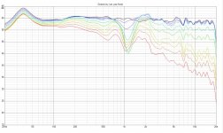
Today I did measurements of the unfiltered drivers and imported them into VituixCAD. No merged near field yet, so do not mind the PEQ peak. Collected measurements where: horizontal 0-90 degrees in 10 degree increments, plus one 180 degree measurement. Vertical +-30, 60, 90 degrees. Some mistakes happened but for now it is okay. After measuring, I rebuild the filters from Hypex Filter Designer in Vituixcad and optimized them, but did not measure yet. Tomorrow. Some things are good, some things are bad:

green listening window, yellow in-room, blue power

interpolations between 90 degree and 180 (the denser lines from green on down)

LR4 @1.1kHz but mor like 1.2 acoustically

What should I be thinking about directivity index and in-room response? Can I do something about it? Also, what causes it?
Best regards
green listening window, yellow in-room, blue power
interpolations between 90 degree and 180 (the denser lines from green on down)
LR4 @1.1kHz but mor like 1.2 acoustically
What should I be thinking about directivity index and in-room response? Can I do something about it? Also, what causes it?
Best regards
Attachments
Last edited:
This means that you should make steep slope for woofer but shallower for the tweeter. That's what i'd do if i wanted to fill that sound power dip and maintain listening window and on axis response flat.
It's coming from different places. Are the ways compatible.. do you have separate polars for W, TH, TV, SystemH&V?
Hello puppetAre you intending to do the drivers individually ... or not?
yes they were measured individually, for designing purposes on a reference axis halfway between the drivers. Without filters the non interpolated set looks like this:


Measurements CDX1-1747 on H6512:
https://mega.nz/file/MVAmgBKb#LZfJZyfYjPpfl59Mhh33F8N7eDfXZvyOuu2hNy3Ra7E
12PR320
https://mega.nz/file/QBAknDAY#l9omO8ot5hhaN2G0Ph2twzRQ0ukONFfu9Hd22D0S_8I
do you have separate polars for W, TH, TV, SystemH&V?
woofer hor

woofer ver pos

woofer ver neg

tweeter hor

tweeter ver pos

tweeter ver neg

system hor

system ver pos

system ver neg

for ease of interpretation vertical, system (nulls)

No interpolations, only genuin measurements. Vertical measurements had some misalignment on the x-axis sadly (meaning: speaker on the side, mic was a little high). but should be a minor issue atm/wasn't too bad.
Last edited:
This means that you should make steep slope for woofer but shallower for the tweeter. That's what i'd do if i wanted to fill that sound power dip and maintain listening window and on axis response flat.
Hey Zvu,
I will try that. But until now it did not help. I do not understand why 12PR320 is breaking down so much at this frequencies where directivity error occurs. As puppet suggested, I also had some measurements with closed port and the influence was negligible. I am not so happy with such a broad deviation and was striving for something better.


Hi, the horn makes pattern flip, loses vertical pattern control above the crossover and thus the dip in power response? Might be some diffraction issues and extrapolation error, because only few measurements on the vertical axis, piling up in the same region? Some timing errors might also cause this, add some delay to the woofer and see what happens 🙂 Check from the phase window that phases align over the crossover region, adjust delay and xo slopes monitoring the phase window. Gif demonstrates effect of small delay to the woofer, smaller woofer and horn but in a way similar situation as you have 🙂
Attachments
Last edited:
Hello tmuikku,
yes, the vertical measurements are not very detailed. It was a balancing act, you know? The heavy speaker on the table from the balcony, on another device and then turning the monstrum above the edge, on reference axis, matching it with some strokes: I was terrified to break something. Maybe it looks better with more measurements, at least first measurement at 30 degree is still kind of decent. But the interpolations of VituixCAD do not add much distress, they just fill in the blanks.
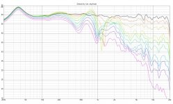
I think the waveguide is loosing pattern control and this causes the mayor problems. Here is another chart, note ERDI horizontal:

Or with vertical removed from DI in options, looks like this. Naturally, ER stays the same:

Phase is okay.

yes, the vertical measurements are not very detailed. It was a balancing act, you know? The heavy speaker on the table from the balcony, on another device and then turning the monstrum above the edge, on reference axis, matching it with some strokes: I was terrified to break something. Maybe it looks better with more measurements, at least first measurement at 30 degree is still kind of decent. But the interpolations of VituixCAD do not add much distress, they just fill in the blanks.
I think the waveguide is loosing pattern control and this causes the mayor problems. Here is another chart, note ERDI horizontal:
Or with vertical removed from DI in options, looks like this. Naturally, ER stays the same:
Phase is okay.
Last edited:
- Home
- Loudspeakers
- Multi-Way
- Digital BSC question