Hello. I acquired a Kenwood KR 2010 receiver (year 1976) in very good aesthetic and working condition.
But I have found that the bias current of the power stage is not similar on both channels.
Channel R - 8 mv (12mA) and channel L- 19mv (28 mA).
The problem is that it does not have an adjustment potentiometer.
How do I adjust it?
Can a potentiometer be inserted for adjustment?
Thank you.
But I have found that the bias current of the power stage is not similar on both channels.
Channel R - 8 mv (12mA) and channel L- 19mv (28 mA).
The problem is that it does not have an adjustment potentiometer.
How do I adjust it?
Can a potentiometer be inserted for adjustment?
Thank you.
Attachments
Yes, but if you rotate it to above 10k bias current will increase rapidly.
Perhaps prevent this with a parallel resistor.
The original design is just adequate for this amp I think.
Perhaps prevent this with a parallel resistor.
The original design is just adequate for this amp I think.
I have placed a 20k multiturn potentiometer in place of R 21 and the similar one on the other channel.
As a result I can calibrate the quiescent current.
I have left it at 17mv on both channels.
As I do not have the manufacturer's indication I have done it leaving 25mA.
Can it be a lot? The amp is hardly warm and its sound is very good.
Thanks for the advice
As a result I can calibrate the quiescent current.
I have left it at 17mv on both channels.
As I do not have the manufacturer's indication I have done it leaving 25mA.
Can it be a lot? The amp is hardly warm and its sound is very good.
Thanks for the advice
Attachments
Preferable is to replace the R23 with a trimmer not R21 because in case of problem on trimmer (open) the IC is preferable to drop to 0mA not to maximum.
OKAY. I will follow your advice.
Thanks.
Is there any idea of the value of the quiescent current? Can it be between 20 and 30 mA ?.
I have read in an article by TNT Audio that raising the quiescent current slightly gives better amplifier performances.
How much could the value be raised without damaging the output transistors?
So many questions is because I am an amateur and not a technician.
Preferable is to replace the R23 with a trimmer not R21 ..
This is right in a general sense, but did you ever see a bias pot failing ?
I did not in 45 years and it is unlikely to happen with a multi-gang item.
You can (add a pot between Q1,Q5 Emitters) -- and it is often done. But first, answer me this: Is the 30mV output offset positive or negative?
The 9mV is probably already better than to be expected for this circuit.
And, I'm sorry as_audio, but I have seen an intermittent bias pot -- and more than one. 😉
I consider it good practice to put the bias pot Base-Emitter because an intermittent, conspicuous increase in crossover distortion is an inexpensive repair. *All outputs and drivers blown* not so much!
Cheers
I concur, and make it a 10-turn cermet trimmer for a long and drift-free life and easy bias setting.Preferable is to replace the R23 with a trimmer not R21 because in case of problem on trimmer (open) the IC is preferable to drop to 0mA not to maximum.
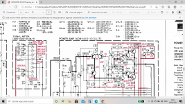
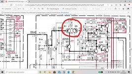
If you were to have R21 go open circuit the bias voltage would jump up lots and the output stages, and/or the fuses, and/or the speaker might get vaporized!
If R23 goes open circuit the bias voltage drops to about 0.7V and you have an underbiased amplifier - less likely to be expensive
(although its still possible to have instability and oscillation)
Last edited:
Voltages are positive on both channels.You can (add a pot between Q1,Q5 Emitters) -- and it is often done. But first, answer me this: Is the 30mV output offset positive or negative?
The 9mV is probably already better than to be expected for this circuit.
And, I'm sorry as_audio, but I have seen an intermittent bias pot -- and more than one. 😉
I consider it good practice to put the bias pot Base-Emitter because an intermittent, conspicuous increase in crossover distortion is an inexpensive repair. *All outputs and drivers blown* not so much!
Cheers
What potentiometer value would you have to place between the emitters of Q1 and Q5. I keep the value of R11 (6k8) and connect it to the moving point of the potentiometer ?.
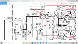
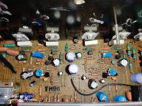
Finally I managed to solve the quiescent current with a multiturn pot on R21 and R22.
Besides, install a potentiometer between the emitters of Q1-Q5 and Q2-Q6 (1k) with its center pin to R 11-R12.
Result: 22mA quiescent current in both channels and offset -1.1mv in L and +0.9 in R.
Many thanks for your contributions.
I am just a fan and not a technician and without your help I would not have achieved it.
I also did a recap of the amplifier board.
Attachments
Last edited:
- Home
- Amplifiers
- Solid State
- Kenwood KR 2010 bias adjustment