Thank you for that. Good point to remember. I plan to move the two large 7w resistors to the underside of the board. I hope to have some time this week to work on it. Thanks for the input!
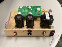
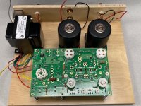
Moved the big resistors to the bottom of the board and finished the remainder. I have mounted the board on stainless screws as pictured to bench test it prior to putting it in an enclosure. Any safety concerns with this setup other than normal electrical safety protocols? I’m getting close!
Attachments

Use clip leads on your meters....clip them where you are measuring with the amp powered down then power up hands off.
Here is a link to the sticky on the tubes forum about general tube safety.
Safety Practices, General and Ultra-High Voltage
One Big point...if you are intent on probing a live tube amp put one hand in your pocket or grab a belt loop on your backside and probe with the other. This implies that you've got the ground/common meter/scope lead clipped somewhere.
Never probe with two hands as high voltage through both arms and across the chest wall is an easy way to die.
The best solution (besides building solid state amps 😉) is to use clip leads.....They may save your life...
Attachments
Last edited:
You can bring the amp to life using a single meter..it just takes time. Having 3-4 meters all connected at once gives you a clear pic of what's going on.
You can buy a couple cheap $7 Harbor freight meters to get started.
Here is the checkout procedure from the Tubelab website:
Checkout | Tubelab
You can buy a couple cheap $7 Harbor freight meters to get started.
Here is the checkout procedure from the Tubelab website:
Checkout | Tubelab
Thanks Boywonder. I have 3 multimeters with clip on leads per George's instructions. Clear on the one hand in my pocket, etc. Getting closer!!
Almost checkout time
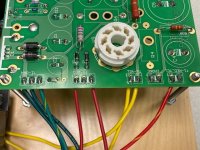
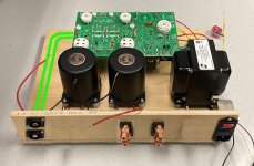
I found a good block of time to work on the final assembly (not the permanent enclosure) for the checkout. Please have a look at my wiring, and let me know if you see any issues. The choke wiring is not pictured, but it will be wired in tomorrow before light off. That said, I have a few unanswered questions:
I'm still a little confused by wiring up the IEC inlet--from the power xformer the black lead goes to hot, and the white lead to neutral? That leaves me wondering how (and what) needs to be grounded on this beast. Does everything get routed back to the ground lug on the IEC inlet?
Does it matter which post (o1/o2/o3) the input signal goes into? What do you do with the signal ground?
I have 3A slo-blo fuses at the ready. I read somewhere but now can't remember whether to fuse the "hot" side, or the "neutral" side. It seems like what I read was kinda counter-intuitive to what I thought. Any harm in fusing both sides?
The yellow/black wire does not get used, right? I can heat shrink the tip, and roll it up and out of the way?
Thank you all for the help! I'm ready to start the checkout!
Attachments
Last edited:
I'm still a little confused by wiring up the IEC inlet--from the power xformer the black lead goes to hot, and the white lead to neutral? That leaves me wondering how (and what) needs to be grounded on this beast. Does everything get routed back to the ground lug on the IEC inlet?
I have 3A slo-blo fuses at the ready. I read somewhere but now can't remember whether to fuse the "hot" side, or the "neutral" side. It seems like what I read was kinda counter-intuitive to what I thought. Any harm in fusing both sides?
The black wire goes to hot and the white wire goes to neutral.
For grounding one common method is "star" grounding.... Use one of the transformer screws (if you don't want another fastener showing on top) or a dedicated ground stud. I use #10-32 screws (I do medical device development and that's the size required by the safety agencies) but a typical #8-32 screw is fine too for this.
Make sure the metal on the underside of the top cover is clean (sand away paint or anodize, etc) and use star type lockwashers between each ground wire when you stack them up. Also use crimped ring type terminals (not spade terminals), that way if the nut happens to get loose the ground wires won't fall off. The star type lock washers are available with the teeth on the OD or ID, either will work fine.
The star type lock washers bite into the ring lugs, top plate and nut assuring a nice bonded joint. So from the top plate down on the stud you'll have star washer-ring lug-star washer-ring lug-star washer-nut for two ground wires. If you have more ground wires just stack up the sandwich with more star washers and ring lugs. You can use a "Keps" nut; that has a built in star washer, but a separate nut and star washer will work fine too.
Keep in mind that from a safety standpoint, the ground connection is the most important connection in the amp. The last thing you want is 400VDC or 110V mains voltage on the exposed top plate.
Fuse the hot side of the AC mains input. If you fuse the neutral side, a failure can still leave mains or transformer voltage exposed, since the hot lead will still be "hot" even with a blown fuse.
You can ground all of your grounds to one point, or have a stud for chassis ground and another for signal ground.
Try to keep your grounds short and terminated to one point....a "star" config. Otherwise you may end up with hum caused by ground loops....they develop by having multiple ground points that are not well bonded together, so slight voltage differences develop causing a little current to flow making hum.
Last edited:
BW, thanks again! I'm working through the checkout procedure, and it says to measure B- across R7. R-7 has been deleted from the TSE-II. Where else can I measure B-?
The end of R6 closest to your red resistor.
I am in the process of hooking up a new TSE-II board for initial power up. You are ahead of me at this point, and my board is guaranteed to have at least one mistake. I rushed to build it using parts removed from two old prototype boards. I already had to fix a couple mistakes.
I am in the process of hooking up a new TSE-II board for initial power up. You are ahead of me at this point, and my board is guaranteed to have at least one mistake. I rushed to build it using parts removed from two old prototype boards. I already had to fix a couple mistakes.
Last edited:
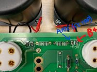
If I were you, I would rearrange the input terminals and speaker terminals as shown in the image below. It's better to keep the input wires further away from power lines.Please have a look at my wiring, and let me know if you see any issues.
Attachments
If I were you, I would rearrange the input terminals and speaker terminals as shown in the image below. It's better to keep the input wires further away from power lines.
Good point.
Jaybird...the inputs are high impedance and can act like antennae...
So when they are routed next to AC lines like the mains voltage or the heater wires, they like to pick up 60 hz hum.
It's AAAALIIIIIIIVVVVE!
Well, shes LIT! Checkout procedure was pretty smooth. No smoke, pops, crackles, etc. I am very surprised that the amp is absolutely dead quiet.
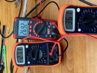
However, I am pretty concerned with my B+ voltage. Several folks said their B+ was pretty high, but came down with the tube load, etc. as the checkout procedure progressed. My B+ is running 361v, and on 45 tubes that can't be good at all. I'll have to go back and scour the threads, but I think George says you can bring the B+ down with capacitor changes. FWIW, I am using a Ruby 5ar4-C as a rectifier--it's all that I had lying around. I'd love everyone's input on the B+ issue.
Thanks Evenharmonics for the advice on the input routing. I will re-route and use shielded wire when the amp goes into it's final enclosure, as well as generally tidy everything up. This iteration was proof of concept and construction for me as this is my first amp build. I was truly expecting a bunch of input hum, but have absolutely none (through these inefficient Mirage bookshelfs--I'm sure my LaScalas will feel differently)
Once I can get the B+ issue sorted, I'd like to add a motor run cap in the power supply, and then it will be on to final assembly!
Thanks all!
*******EDIT**************
Reading now, it looks like I may need to measure the B+ voltage at the tube, not across the resistor as in the checkout procedure. Is that right as the B+ will drop as it works it's way through the circuit and arrives at the 45's?
--Jaybird
Well, shes LIT! Checkout procedure was pretty smooth. No smoke, pops, crackles, etc. I am very surprised that the amp is absolutely dead quiet.
However, I am pretty concerned with my B+ voltage. Several folks said their B+ was pretty high, but came down with the tube load, etc. as the checkout procedure progressed. My B+ is running 361v, and on 45 tubes that can't be good at all. I'll have to go back and scour the threads, but I think George says you can bring the B+ down with capacitor changes. FWIW, I am using a Ruby 5ar4-C as a rectifier--it's all that I had lying around. I'd love everyone's input on the B+ issue.
Thanks Evenharmonics for the advice on the input routing. I will re-route and use shielded wire when the amp goes into it's final enclosure, as well as generally tidy everything up. This iteration was proof of concept and construction for me as this is my first amp build. I was truly expecting a bunch of input hum, but have absolutely none (through these inefficient Mirage bookshelfs--I'm sure my LaScalas will feel differently)
Once I can get the B+ issue sorted, I'd like to add a motor run cap in the power supply, and then it will be on to final assembly!
Thanks all!
*******EDIT**************
Reading now, it looks like I may need to measure the B+ voltage at the tube, not across the resistor as in the checkout procedure. Is that right as the B+ will drop as it works it's way through the circuit and arrives at the 45's?
--Jaybird
Attachments
Last edited:
If the measured B+ is without the 45s installed, it will drop once you install them. This is where a variac comes in super handy.
Without the tubes installed..there is no current flowing so the power supply is unloaded.
You can lower B+ several ways....a 5U4 rectifier is plug and play and drops more volts than a 5AR4.....or as mentioned reduce the value of the first capacitor after the rectifier. This is where PSUDII comes in handy.
Last edited:
Boywonder, the 361 volts pictured are with all of the tubes installed and the amp running. I have it on a variac, so can roll the voltage down a bit. Is the B+ the same whether measured across R36 or the tube? Thinking on it now, I may have a 5u4 in a box somewhere. Maybe George will chime in with a recommended Cap value (and location) to help tame the B+. thanks for the input!
If you have extra PS caps try a lower uf value for the first cap after the rectifier.
5U4s are directly heated so they bring the voltage up faster. 5AR4 indirectly heated.
5U4s are directly heated so they bring the voltage up faster. 5AR4 indirectly heated.
After running the amp for several hours, I am in love with it. I just thought I had experienced a "deeper" soundstage--it's crazy! I'm still struggling with adjusting my B+ to get it exactly where I want it. I switched C4 to a 4.7uf from the original 47uf, and it brought the B+ down to about 315v from 360v when biased. Today I dropped in a 600v .47uf cap that I had lying around, and it dropped the B+ down to about 235V. Is there a better way than trial and error to get the B+ into the 275-300v range? I'm still running it in a temporary plywood enclosure, and am anxious to get the final enclosure built. Thanks all!
Is there a better way than trial and error to get the B+ into the 275-300v range? Thanks all!
Yes download and use Duncan amps PSUDII (power supply designer II).
If you are interested I can post the schematic for PSUDII here for the TSE and you can't tweak the values of the first cap to determine B+.
Are you using a choke input? How many henries?
Last edited:
BW, thanks as ever for the assistance. I have Duncan's PSUD on my laptop, but the learning curve is pretty steep for me. If you can post the schematic, I can monkey around with it if I can figure out how to change the values of the caps. I am running the Triad Magnetics C-14x that George recommended in the build materials. It is a 6H choke @ 200ma.
As another note, it seems that the noise floor at idle increases as I decrease the capacitance of C4. I'm kinda funny about wanting the amp to be silent at idle. Is there another way to address the B+ and keep the added capacitance? I don't know how people install the huge motor run caps without adding massive amounts of B+...........
As another note, it seems that the noise floor at idle increases as I decrease the capacitance of C4. I'm kinda funny about wanting the amp to be silent at idle. Is there another way to address the B+ and keep the added capacitance? I don't know how people install the huge motor run caps without adding massive amounts of B+...........
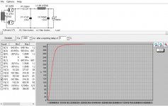
Here is a start for the PSUD model......
Double click on transformer to change voltages and resistance (I guessed on resistance...you can measure it on your transformer)
You can right click on "sections" of the power supply to add/subtract LC or RC stages.....right click and add an LC section....
You can also double click on components to change their value. The 5AR4 is a built in rectifier choice....but first right click on the rectifier section and select "vacuum tube full wave"
Right click on the default 5K load and select "constant current"
The 84ma is a guess of 12ma each for the 5842s (24ma total) + 30 ma each for the 45's (60ma total)
To display the voltage curve at i1 check V(i1) then click the simulate box.
Attachments
- Home
- More Vendors...
- Tubelab
- Jaybird’s TSE-II build...here we go!