Hoping to get some insight and check if I am on the right track in turning a very well built mid 90's 200 watt at 8 ohm, 325 at 4 two channel commercial power amp, into a great formidable high fidelity product.
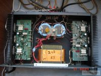
Currently the amp has no issues and is in great condition. The amp uses a pair of Motorla JFETs on it's input with a quad of Sanken bipolars as outputs. Power transformer is nicely over sized with a chassis mounted 35amp bridge rectifier, though power supply filter capacitance seems a bit low at only 10,000uf. From the schematic and parts quality, it looks like this amp would really come to life with just a few simple modifications.
Below is my proposed list of changes that should IMO make this amp sound much better. Any input to would be greatly appreciated.
1. bypass input balance circuits and level pots. Wire an RCA jack directly to pins 7&9 (direct coupled). Should I install a 10k ohm resistor across 7&9 for matching? Will there be any issue omitting a 10uf coupling capacitor on the input? (there will be no DC at the jack)
2. Either swap out the current 10,000uf Mallory filter caps for same value Mundorf Mylytic HC, or install 22,000uf Kemet (same physical size as the factory installed Mallory)
https://www.mouser.com/ProductDetail/KEMET/ALS36H223L3C075?qs=b8LFrSqGEF8HOXdlWVz1Bw==
And lastly, bypass the speaker fuse.
Thank you in advance for any input as to whether or not I'm on the right path.
Attachments
180k for Re degeneration has to be the highest I've ever seen. Isn't the LTP going to be a noise monster as a result?
It's just going to sit there, for decoration, I guess. The other has a big cap between the emitters, so it'll do all the work at AC. I wonder what the output DC offset is.
2 pairs of output devices without protection circuit for "325W@4ohms" is... optimistic.
> The amp uses a pair of Motorla JFETs on it's input
The FETs are only for muting, the input pair is BJT.
2 pairs of output devices without protection circuit for "325W@4ohms" is... optimistic.
> The amp uses a pair of Motorla JFETs on it's input
The FETs are only for muting, the input pair is BJT.
The FETs are only for muting, the input pair is BJT.
You are correct sir. An embarrassing oversight.😀
I suspect there ought to be a counterpart to C13 up there... possibly called C10 as that number appears to be unused.The schematic is... creative, especially the top LTP 😀
I would prefer tweaking the balanced input circuitry over bypassing it... a balanced input is a good thing to have and easy to make use of even if you only have unbalanced outputs. The screw terminals provided make it easy to hook up just about anything. I would suggest adding some AES48-2005 compliant female XLR connections (pin2 to + and pin 3 to - using twisted cabling and pin 1 to chassis, I hope the backplate has a good electrical connection).
C1, 2, 14 could stand being a bit bigger. (Some of the small electrolytics may already be toast in general.) The TL072 isn't the last word as an input opamp either, being a bit noisy and breaking a bit of a sweat at high levels, although there would still be a decently large sweet spot as-is (peak input approx. +10..+12 dBu, at which point dynamic range reaches the desired ~110 dB). I would try some of the "old guard" of medium-low-noise parts of moderate power hunger yet decent slew rate... LM833N or MC33078. Not sure whether the layout would support an LT1358.
There is zero RF suppression of any kind on the input. For starters, I would suggest maybe 47 pF from each of + and - directly to chassis, as well as maybe 1 nF from GND directly to chassis. A few turns of the twisted (+, -) wiring through a ferrite core would not go amiss either.
The speaker fuses appear to be the only protection this thing has in case of catastrophic failure. I would strongly advise looking into retrofitting a speaker protection board, maybe even something solid state relay based.
Something I do not like at all about the power amp circuit - the elephant in the room if you will - is the bootstrapped driver stage (TIP31/32 supplied from +/-5 V around output). You do not normally see this for good reason, as it results in substantially worsened load immunity, which is less than luxurious in an EF2 output stage to begin with. It probably was good enough for PA, not so much for hi-fi. I would suggest an extensive rework using some different drivers which can operate directly on +/-75 V (maybe MJE15031/32?), in which case you may also be able to ease up on C20/21 (a bit of a kludge that may have been necessitated by the lack of any passives in series between drivers and outputs, as quite commonly found otherwise). I think the clipping indicator would work quite happily even with the drivers having their collectors connected elsewhere.
It goes without saying that this mod isn't for the scopeless or the faint of heart, but as they say - no pain, no gain.
A better photo of the input stage area (Q3-Q6) would be appreciated, I can't even tell whether thermal coupling is as it should be.
Yes to your recommendations 😀
> The TL072 isn't the last word as an input opamp either
I've had good results replacing junk opamps like 4558 in old gear with some of the new OPAs from TI (those with lots of zeros in the THD). In these old board, decoupling caps are a mile away, so I picked the low gain bandwidth ones like OPA1642. Works well. Wouldn't recommend the 50MHz ones.
> I would strongly advise looking into retrofitting a speaker protection board, maybe even something solid state relay based.
Personally I would reuse just the case and maybe also the transformer and power transistors...
> the bootstrapped driver stage (TIP31/32 supplied from +/-5 V around output). You do not normally see this for good reason, as it results in substantially worsened load immunity, which is less than luxurious in an EF2 output stage to begin with.
Ooh I hadn't noticed it. There is even a mechanism to increase crossover distortion and inject dirty current in ground traces via R27...
Why do bootstrapped drivers lead to "substantially worsened load immunity"? (asking cause I think I'm gonna use some in my next project)
I think the protection circuit for this amp is when the bootstrap caps discharge into the power transistor bases. "Delayed action current limit!"
Maybe it's just me -- and apologies to the designer if she/he's reading this -- but it looks like there was a kind of *symmetry seduction* going on. That the notion of complete symmetry was so compelling, the designer just couldn't let go of it! Even as more and more kludges and Band-Aids were required to garner a modicum of performance / stability -- way past the point where the circuit sections function as originally imagined or intended.
As it is, Q7 and Q8 are pretty much just a CCS. Q3 and Q4 have no appreciable differential function. The note about a C10 between their Emitters is a good one -- maybe 1 or 2,2uF in series with 68 to 150R. THEN it would make a differential contribution.
But, there is already a C10 between the off-board Volume pot and the '072 output.
I also think the same treatment would be worth trying in place of C13. As it is, Q5 / Q6's dynamic range is frightfully limited, and they have no ability at all to control at DC. Plus, there's only so much they can do with 404uA to 425uA, which is the full range available for rail-to-rail output swing.
R27 is a whopper! I must be reading that wrong: It's going to want 27A through one or the other 1N4148's as the output swings to + or -68V !?
Having a hard time figuring why you'd want to omit the speaker fuse. Is it somehow damaging sound quality? 😉
Just my 2¢ ..
Cheers
Last edited:
- Home
- Amplifiers
- Solid State
- Modifiying a commercial amplifier for Hi-Fi