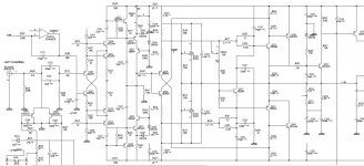
Hi, I couldn't drop the bias current less than 6mv over output resistor for only one channel. I've tried for weeks 🙂 When I want to adjust semipot it drop the 6mv and increase again. Min value is 6mv (about 90ma or more) over 0.067 ohm resistor (R196). The other channel can drop to 1mv or less.
I changed all elect. caps and most of transistors. (not earlier stage of amp. and not power output transistor Q139,Q141). But, all looks like ok. resistors are ok.
After weeks I want to ask here. I couldn't solve 🙂 Any idea will be very helpfull. note that there is no problem in sound! I add the schematic here;

Last edited:
"Your emitter resistors are unusually low.
Decrease R 181. "
Semipot is not min/max value. I can change r181+vr300 value. I measured the voltage on R181&R183, resistors working 🙂
Decrease R 181. "
Semipot is not min/max value. I can change r181+vr300 value. I measured the voltage on R181&R183, resistors working 🙂
The word Semipot is unknown to me.
If you want to decrease the voltage of bias spreader Q133
resistance in the base emitter branch has to be decreased.
This means the sum of VR103 and R181 has to decrease.
Bias current will fall accordingly.
Check for dc offset at amp output. If some positive offset
current is going to ground through a resistive dummy load
it will show as small voltage on this emitter resistor.
There is a dc servo, but two "connection dots" are missing
in the schematic of post 1, between R11 and Q105 base and
between C105 and Q107 base. The schematic is not consistent
in this respect.
You did not explain : is this a commercial amp, a kit or your
own design. This will make it easier to give advice.
Thank you for help,The word Semipot is unknown to me.
*Sorry, I used semipot, bec. service manuel named as semipot. Trimpot, variable resistor, pot.
If you want to decrease the voltage of bias spreader Q133
resistance in the base emitter branch has to be decreased.
This means the sum of VR103 and R181 has to decrease.
Bias current will fall accordingly.
* When I continue to decrease, bais current starts to increase. min about 90ma. (sorry perhaps due to my English. when I decrease pot value, bais current decrease up to 90ma, after that value if I continue to decrease, bais current starts to increase. this is my problem).
Check for dc offset at amp output. If some positive offset
current is going to ground through a resistive dummy load
it will show as small voltage on this emitter resistor.
* very good advice I will check.
There is a dc servo, but two "connection dots" are missing
in the schematic of post 1, between R11 and Q105 base and
between C105 and Q107 base. The schematic is not consistent
in this respect.
* I'm not sure...
You did not explain : is this a commercial amp, a kit or your
own design. This will make it easier to give advice.
*NAD C352 and service manuel.
NAD C352 is essential information for post 1.
Many people will know it.
The bias adjustment is at risk, if the pot fails power
transistors will get highest current, are there some
fuses for protection (schematic not complete) ?
Apart from this - if the "minimum" bias set is not at
extreme pot position it seems something is going wrong.
Many people will know it.
The bias adjustment is at risk, if the pot fails power
transistors will get highest current, are there some
fuses for protection (schematic not complete) ?
Apart from this - if the "minimum" bias set is not at
extreme pot position it seems something is going wrong.
NAD C352 is essential information for post 1.
Many people will know it.
The bias adjustment is at risk, if the pot fails power
transistors will get highest current, are there some
fuses for protection (schematic not complete) ?
Apart from this - if the "minimum" bias set is not at
extreme pot position it seems something is going wrong.
I will remember this for my next posts.
There are 4 fuses at output of power supply,.
Yes, yes something wrong. I'm searching resistor fail now. But, they all looks fine. I assume seramic and polyester capacitors are ok. I also assume that power transistors are not partial fail. Sound is perfect, a little hot 😡
I see that you posted about issues with NAD C352 before.
In a serious attempt to get help from forum members all
essential information should be known. Multiple threads
for the same amp are not useful in this respect.
In a serious attempt to get help from forum members all
essential information should be known. Multiple threads
for the same amp are not useful in this respect.
this is same amplificator;1) heat problem 2) bais problem. They are different problems. If they will be same problem, I will continue with first head off course.
Heat problem is normal operation of amplifier, I assumed solved.
Heat problem is normal operation of amplifier, I assumed solved.
I assume I found something; first I remove zobel network, this is not the problem. Second, when I measure bais, I pressed the cooler of transistors (not power transistors cooler, one before). With pressure bais changing 🙂
I will think about this, (solders?). Perhaps it will close my problems with this amp. (NAD C352).
I will think about this, (solders?). Perhaps it will close my problems with this amp. (NAD C352).
NAD amps of this series are not without problems.
Quite a few people here may know about it.
However it is useful to know the complete history if
you worked on his amp before. The problems can be
interdependent in this case. It is needless to assume
that no mistakes have been made. So : everything in
one thread.
Quite a few people here may know about it.
However it is useful to know the complete history if
you worked on his amp before. The problems can be
interdependent in this case. It is needless to assume
that no mistakes have been made. So : everything in
one thread.
🙂 Veysel, You got it!!!
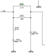
I take out C143&C145. Now, bais current started decrease 🙂
SO, what I will do now? will I change capacitors or what do you advice?
View attachment 948477
Assuming you are doing the circuit correctly, this is a design error, adding one or a few compensation capacity may or may not solve the problem, try
- Home
- Amplifiers
- Solid State
- Bias current problem


