Hello Community,
I'm trying my hand at building a kit from ebay. Eventually, I want to build something much nicer, but thought I should get my feet wet first. I'm at the infancy of this electric adventure and my knowledge is very limited.
That said, I've tried watching as many related videos as I could find and read extensively here on DiyAudio to try to solve my problem. I've not been able to do so. So I turn to you for help.
After putting the amp together, switching it on to no (very little) hum and no smoke. I turned up the volume and had music. I was stoked. However, I quickly discovered that the right channel is playing much louder than the left and the magic eye on the right is inactive.
So I bought an oscilloscope.
It seems the signal is clipping on the right channel at about half volume. So I feel like the left side is wired correctly and the right not.
I tested voltage throughout. Left and right do not show the same voltages.
At pins (R)1 and (L)6 on the 6n1 (ecc85), 1 shows 88.4v and 6 100v.
R: 3 and 8, 1.5v and 101.9v
L: 8 and 3, 1.65v and 95.7v
C1 210v
C2 91v
C3 199v
C4 101v
On the tube side of resistor 6 and 8, 9 and 10 there is a difference on both sides.
R6 87.7v
R8 100v
R9 91v
R10 101.7v
Pins 3, 7, 9 on the 6p14s are all very similar
R
pin 7 on both is 311v
L
pin 7 on both is 312v
R
pin 3 on both is 10.5v
L
pin 3 on both is 10.3v
All pin 9s are 298v
Finally, there is no signal reaching the magic eye circuit coming from R5. There's a faint signal reaching the resistor but nothing on the other side.
The signal seems to already be at half coming off pin 3 before going into R3.
There is equal signal at R1 and R2
When I hook up the signal generator, the right channel signal can be heard much louder coming from somewhere in the amp (output transformer?)
Thank you for any help or ideas you can give me.
Will in Korea
Attachments
"6N1 " ?--- are you not talking about the Russian 6N1P which is not equivalent to the ECC85 --are they branded =ECC85 ?
I'm not home at the moment but the description on eBay shows 6N1-M. The graphic looks the same in the description and from what i remember seeing on the tube. I'll verify when I'm home in a couple hours.
...
Finally, there is no signal reaching the magic eye circuit coming from R5. There's a faint signal reaching the resistor but nothing on the other side.
The signal seems to already be at half coming off pin 3 before going into R3.
There is equal signal at R1 and R2
When I hook up the signal generator, the right channel signal can be heard much louder coming from somewhere in the amp (output transformer?)
Thank you for any help or ideas you can give me.
Will in Korea
The 'signal' for the magic eye comes from the output of the transformer T1, not from R5.
The resistor R5 is the 'feed back' resistor. It takes a small amount of voltage from the output transformer and feeds it back into P1A.
If working correctly it will reduce the gain (and hence volume) of the amplifier and reduce distortion.
I suspect that the Left channel is correct. And that the Right (louder) channel is wired incorrectly round the output transformer / feed back part. Your description suggests you have the secondary wired the wrong way round?
I believe the Chinese 6N1-M is not at all like the Russian 6N1-P. The Chinese tube is is kind of close to an ECC85/6AQ8. I think your OPT wiring is what might be what is giving you grief. Try swapping the 6N1-M tubes between channels to see if that makes a difference. I've seen a lot of variability in some of the Chinese small signal tubes.
The 12AT7 is "sort of" like a 12 volt filament version of the 6AQ8/ECC85. Not real close but would work well with filament rewiring and a couple of resistor changes. See the SPP amp on the Tubelab forum on this site. It uses a 12AT7 driving EL84s.
S.
The 12AT7 is "sort of" like a 12 volt filament version of the 6AQ8/ECC85. Not real close but would work well with filament rewiring and a couple of resistor changes. See the SPP amp on the Tubelab forum on this site. It uses a 12AT7 driving EL84s.
S.
If what you say is true where has the International Tube/Valve Designation coding gone ??
There is a sort of equivalent list for Russian tubes but would you mind directing me to a list of "Chinese " tube designations ?
In the UK at least we were directed to international standards by Pro-Electron if this is now defunct what has taken its place- -----Chaos ?
Ah ! I see its now EECA who owns/controls it ( Pro-Electron ) ---not doing too good a job then if they haven't brought China into line ,something wrong here as this type of (non ) Standard is not safe.
Russian 6N1P and Chinese 6N1 are the same spec., and are quite close to ECC85. Check the data sheets. Much less mu than 12AT7 (35 vs 55)
6N1P is electrical equivalent to ECC40 , not "close" to ECC85 only if you think all small triodes except maybe 12AX7 are similar 😀
But this is not very important , it is a good tube anyway .
For the original issue , hard to figure out what mistakes you did with the amp ... the signal should be traced from input to output with the scope ( negative feedback disconnected ) on both chanels to see where are not longer the same .
The DC voltages should be closer , but only from that you can't know where is your problem .
Last edited:
I suspect there are none. It's all over the place basically.would you mind directing me to a list of "Chinese " tube designations ?
6N1 and 6N2 in particular are indeed 6N1P and 6N2P clones respectively (at least by the datasheets). But, say, 6N4 has nothing to do with 6N4P - in fact it is 12AX7/ECC83 clone, with dual voltage heater system and everything.
So this is a 6N1 with no other designation. I've tried swapping tubes. No change.
I'll check the opt wiring today. Thanks for the help
I'll check the opt wiring today. Thanks for the help
6N1P is electrical equivalent to ECC40 , not "close" to ECC85 only if you think all small triodes except maybe 12AX7 are similar 😀
.
Of course a tube with 2.9mA/v gm is the same as one with 4.9mA/v.
That's the view of amps from China
Last edited:
So its "open house " in the definition of tubes from China ?
That leaves the system open to corruption when Standards are deserted ---"your tube amp doesn't work --sir ? we are not to blame as xyz tube is meant for abc operation" or our tube is faulty ?--maybe you don't understand our consigned engineering definitions of the functions of our tubes ?"
I remember one TV shop I worked in where faulty valves were "BVA,d"= British Valve Association returned as a manufacturing fault and a small advice note listing the make/type and fault condition was listed.
Changed days .
Ask the Russians, Chinese, British and Americans what a 6N6 is and you will get at least three different answers.
How about a 6S4?
I believe international standards went out the door with the start of the Cold War
How about a 6S4?
I believe international standards went out the door with the start of the Cold War
Last edited:
Alan will probably turn out to be right. You can confirm that with your o'scope, feeding the same signal into both channels and looking at the speaker output terminals. Your DC voltages look fine, so you have the luxury of poking around without worrying about damaging the machine. But be safe!
I once lived in Daejon, about 50 years ago. I still think of those days often.
안녕히 계세요, and all good fortune,
Chris
I once lived in Daejon, about 50 years ago. I still think of those days often.
안녕히 계세요, and all good fortune,
Chris
Update.
I unsoldered the feedback wire that went to a pcb board 8/4 ohm switch. Perhaps it was not soldered correctly because after wiring it directly to the positive and negative binding posts, the sound has equalized and is playing correctly. Awesome.
However, the right magic eye is still blind.
Now I know for certain that these Douk amps sound pretty meh. They have a hard time pushing my Continuum IIs. But those speakers aren't the easiest to play. My record player sounds like mud with this amp. Guess it's time to build a preamp.
Thanks again for your help.
I once lived in Daejon, about 50 years ago. I still think of those days often.
안녕히 계세요, and all good fortune,
Chris
Anyoung my friend. You wouldn't recognize the country now. Not to be presumptuous, but were you stationed here? I had a number of uncles stationed here, all with fond memories. Great place to live especially as a mountain biker. Endless trails and all mountains are public access.
Yes, I was installed on the top of a mountain, maintaining US military telecom links, cheek-to-cheek with a ROK military compound doing the same. In the morning, we would watch the clouds rise up to meet us.
This was towards the end of the second Korean civil war, which most Americans haven't even heard about. Police directing traffic at intersections had slung M-16's and vigilance was high. Walking around on the mountain at night would have been deadly - the Americans were sleeping, but the ROK's weren't.
At that time and in that place, there were almost no private cars. Ox carts and old women with giant bundles of firewood on their heads, taxis. Nobody was going hungry, but war had pushed everyone very hard. It would be a great joy to go back and see how well the country is doing now. To go from wartime destruction to the most vibrant country on the planet, all within one lifetime, is something to be both proud of and amazed at.
I'm tearing up, thinking about it,
Chris
After saw EBAY of MrAzeker about EL84
I have question about Chinese design 6P15. If it is irrelevant to the topic, Please delete my post.
Question is how to use 1K trimpot to adjust the balance between 2 tubes of 6P15
1. which 2 point to measure the balanced voltage between 2 tubes.
2. If using B+ of 320VDC, the value of 2 checking points should be how much (approx) in volts.
Thank you and sorry if irrelevant to topic
Attachments
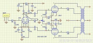
.....which 2 point to measure the balanced voltage between 2 tubes......
The circuit is not set up to measure current. (Was this ever built?)
Add two 1 Ohm or 10 Ohm resistors. Measure cathode to cathode.
How much unbalance is too much? Does the plan give any idea? I would first measure -across- one resistor to get the tube current. Say 30mV. Then figure 5% of that. 1mV or 2mV. Try to get the differential reading down in that range. (However no tubes are stable to the last mV.)
Attachments
- Home
- Amplifiers
- Tubes / Valves
- 6p14/EL84 13W Magic Eye From ebay