I've built a SE amp using 6L6gc and my plate voltage is about 50V less than it should.
I have 250VAC from my power trafo to full bridge rectifier, into a 150uF capacitor, so it should be around 360VDC: but when i measure it, its only 315VDC. The quiescent current is 65mA. The rest of the amplifier draws about 5mA. Ripple is about 3-5VAC.
Do i have something wrong or does the tube just load the power supply so much? My power trafo's 250VAC is rated 150mA, so it should be plenty.
Are you using a solid state or valve rectifier?
It might help to see a circuit diagram of the PSU configuration.
It might help to see a circuit diagram of the PSU configuration.
You are measuring the on load voltage, not the theoretical voltage.
Measure the voltage off load and it will be 1.414 X the AC voltage.
Measure the voltage off load and it will be 1.414 X the AC voltage.
(21/2) (250) = 354
I'm guessing poor regulation behavior and copper losses in the power trafo are the causes of what's observed.
I'm guessing poor regulation behavior and copper losses in the power trafo are the causes of what's observed.
Well, 360V without load maybe, when a current is flowing the resistance of the primary and secondary reduce the voltage.
measure the DC-resistance of the secondary, I guess 50 ohms, then double it to account for the primary.
The current flows only short time during a cycle and is maybe 6 times higher.
6*70mA*100R = 42V + 2V(diodes)= 44V less than idle.
You will need a transformer with 280V I guess
measure the DC-resistance of the secondary, I guess 50 ohms, then double it to account for the primary.
The current flows only short time during a cycle and is maybe 6 times higher.
6*70mA*100R = 42V + 2V(diodes)= 44V less than idle.
You will need a transformer with 280V I guess
Last edited:
Are you using a solid state or valve rectifier?
It might help to see a circuit diagram of the PSU configuration.
Solid state full bridge rectifier. I will post PSU diagram later.
Is that nominal (under 150 mA load) AC voltage or measured off-load one?I have 250VAC from my power trafo
Solid state full bridge rectifier. I will post PSU diagram later.
Thanks, it could be useful.
Is that nominal (under 150 mA load) AC voltage or measured off-load one?
And:
Measured while amp was on.
This is all important. We need to know the actual voltage you measure on the input to the bridge while the DC voltage is only your measured 315 volt dc.
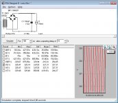
I'm assuming the the transformer is as per this image but a single winding and four diode bridge is similar. Load current is at the right and is considerably higher than your example.
Attachments
You're only 12% low, which could be normal depending on your transformer regulation and wall voltage.I've built a SE amp and my plate voltage is only 315VDC it should be around 360VDC:
Ok this propably explains it. But is it normal that i still measure 250VAC at the bridges input while under load?
Are you using a solid state or valve rectifier?
It might help to see a circuit diagram of the PSU configuration.
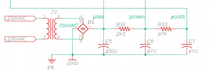
Here's the PSU, also measured the power trafo. Primary was 55ohms and secondary 260ohms? Sounds quite alot, maybe i need to disconnect it from the bridge?
Attachments
The ripple current into the first capacitor is significant and will cause a large voltage drop through the transformer.
Here's the PSU, also measured the power trafo. Primary was 55ohms and secondary 260ohms? Sounds quite alot, maybe i need to disconnect it from the bridge?
So that is pretty conventional. If you really have 250vac going into the bridge then the DC coming out has to at least peak at close to 350 volts.
So what is going wrong. The only thing I can think of is that your 250vac as measured isn't a true result. Maybe the peak of the AC from the transformer is getting 'flat topped' due to voltage sag and saturation in the transformer but your meter is interpreting the non sine shape as something different.
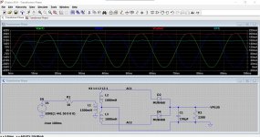
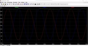
This shows the theoretical result of 250vac applied to your set up. The load is drawing close to 90 milliamps. Second image is a close up of the rail voltage.
I wonder what your scope would show looking at the secondary voltages but be careful if you try.
The scope will be looking at the voltage from the zero volt (ground) point. Do not attempt to float the scope across the secondary unless it is a battery powered and fully isolated scope.
It would be interesting to see if the voltage was significantly clipped at the peaks.
Attachments

My DMM is not true RMS, i can borrow one though. I also have analog scope + isolation transformer, so when i get the time i could hook it up and take a look.
If that matter, the power trafo of my amp is TOROIDAL. Indel TSTLA 60/002 to be exact.
Well, i guess i just change the 6l6gc anode resistor to smaller one to compensate for the lower plate voltage.
If that matter, the power trafo of my amp is TOROIDAL. Indel TSTLA 60/002 to be exact.
Well, i guess i just change the 6l6gc anode resistor to smaller one to compensate for the lower plate voltage.
I'd expect something like a third or quarter of that. Try to remeasure with the transformer disconnected.secondary 260ohms? Sounds quite alot
Digital Multi Meters do not like to measure Ohms on a power transformer, or on an output transformer.
Short the Primary wires first, then measure the Secondary DCR.
Remove the short.
Call that S Ohms.
Now, short the Secondary wires, then measure the Primary DCR.
Remove the short.
Call that P Ohms.
Suppose the primary is 230V, and the secondary 250V.
250V/230V = 1.086
Then multiply the primary DCR, P Ohms by 1.086.
S Ohms + (P Ohms x 1.136) = the approximate Total DCR that will drop voltage from the unloaded 250V secondary versus the loaded secondary.
It is the Total DCR x the Peak capacitor current that gives the voltage drop, when you load the B+.
With no load on the B+ (open circuit), a solid state bridge, a 250VAC secondary, and a filter cap,
the voltage will be 353VDC.
Last edited:
On your next project, try using a Choke Input Filter for the B+.
Be sure to use a choke that is made for it, and be sure to use enough Henrys to get critical inductance, or a little bit more is good too.
You will need higher secondary Volts to get the same B+ Volts, but the supply will be better regulated versus changing load currents.
The rectifier current is very smooth, no transients and high frequency interference.
I use choke input filters whenever possible.
Capacitor input filters have large transient currents, with high frequency components that often get into the signal circuitry.
Last edited:
- Home
- Amplifiers
- Tubes / Valves
- Power tube supply voltage drop