Hi,
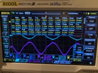
I've almost got no hair left after trying to figure out why my amp's right channel oscillates at 50Khz.
I've recapped it, all resistors are original but measure within 1%. Voltage levels seem fine.
When the amp oscillates, it gets pretty endemic, and is evident in the entire chain, from input to output. Even left channel gets affected a bit.
Now, for some facts:
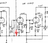
I've run in so many circles, I don't know where to go. I'm also an amateur, so it's probably something very evident I'm missing. It seems to me there are no grid stoppers here - or, in the case of V4, I guess the volume control kind of acts like it. That's the closest I've come to something that makes sense based on whatever literature I can get my hands on (combined with my limited skillset).
I've attached the schematics, plus a few pics. Hope anyone can shed some light on this. It's a beautiful amp, but I spend way too much time during the day pondering about what's wrong with it, and finding no answer
I've almost got no hair left after trying to figure out why my amp's right channel oscillates at 50Khz.
I've recapped it, all resistors are original but measure within 1%. Voltage levels seem fine.
When the amp oscillates, it gets pretty endemic, and is evident in the entire chain, from input to output. Even left channel gets affected a bit.
Now, for some facts:
- Removing V4 (amplification after volume control + inverter) takes away the oscillation, but then right channel is of course dead.
- Bypassing cathode resistor of V4a (i.e. disabling the feedback loop) also takes away the oscillation.
- Swapping tubes around, or putting in new ones, has no effect
- Running the amp at a lower voltage (<180V, this is a 220V amp) lets it work fine within a certain range of the volume control (not too low, not too high)
- Input signal strength does not affect oscillation. The only thing that I can do to affect it directly is to adjust the volume knob. Low volume and high volume both increases oscillation, somewhere in the middle either lowers it a bit, or, if I run amp at a lower line voltage, removes it.
- Oscillation doesn't start immediately, amp works fine for a few seconds before it kicks in.
I've run in so many circles, I don't know where to go. I'm also an amateur, so it's probably something very evident I'm missing. It seems to me there are no grid stoppers here - or, in the case of V4, I guess the volume control kind of acts like it. That's the closest I've come to something that makes sense based on whatever literature I can get my hands on (combined with my limited skillset).
I've attached the schematics, plus a few pics. Hope anyone can shed some light on this. It's a beautiful amp, but I spend way too much time during the day pondering about what's wrong with it, and finding no answer
Attachments
Last edited:
Are you testing this unloaded? If so, add Zobels across the output transformers' secondaries, maybe 20R in series with .047uF across the 16Ohm taps to common. Actually, just do it anyway. It's ridiculous to expect a pentode amplifier with loop feedback to operate properly without. That was the bad old days. "The past was the worst" - Simon Whistler
All good fortune,
Chris
All good fortune,
Chris
Hi,
did you had open the nfb path and see what happend then? Everything which change the phase characteristics come into provision .There are the kathode r c of v4, the feedback R and the coupling capacitors. Check them for leaks or value change.
The speakers may also to be consider in the fault. Check with load resistor instead a speaker.
73
Wolfgang
Hi,
I would put the Zobel to the primary side of the opt. set to 20kHz.
8,2k series with 1nF.
But the amp had once work and the other channel does work. So why try to convert the circuit to compenste the error.
A better solution is to find the fault.
As I wrote before, even a defective devider network in a speaker can lead an amp to oscillate.
73
Wolfgang
The first obvious thing to check are the 100pF caps before the phase splitter tube
I have changed them, but it didn't help.
Hi,
did you had open the nfb path and see what happend then? Everything which change the phase characteristics come into provision .There are the kathode r c of v4, the feedback R and the coupling capacitors. Check them for leaks or value change.
The speakers may also to be consider in the fault. Check with load resistor instead a speaker.
73
Wolfgang
As said, when I disabled the nfb (by removing the cathode resistor), the oscillation stopped. I have replaced all capacitors, and double checked the cathode bypass as well, in case it was damaged. All checks out fine.
I'm not using speakers, but 8 ohm power resistors.
The amp worked "fine" before recapping - i.e. no oscillation as far as I know - was sound in speakers, now it's not in the oscillating channel. However, I've double checked and everything is in place where it should be, and measuring correct with DMM.
Hi,
I would put the Zobel to the primary side of the opt. set to 20kHz.
8,2k series with 1nF.
But the amp had once work and the other channel does work. So why try to convert the circuit to compenste the error.
A better solution is to find the fault.
As I wrote before, even a defective devider network in a speaker can lead an amp to oscillate.
73
Wolfgang
Yes, I would like to retain this as original as possible. That's part of the charm, and the amp is in pristine condition as well..
You might want to try to increase their value.I have changed them, but it didn't help.
Modern electrolytic caps are generally more "wideband" than the old ones, so you may have shifted some poles with recapping just enough to get oscillation.
It a problem is with the negative feedback. Remove both feedback resistors 7K from the OPT. Check that the gain of both channels is the same. Do this for both 1KHz and say 15KHz. Check the 100p+30k in series.
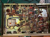
I can see on your photo on one channel the 100pF is not taken back to the correct place. Its going to the cathode instead of the grid.
It a problem is with the negative feedback. Remove both feedback resistors 7K from the OPT. Check that the gain of both channels is the same. Do this for both 1KHz and say 15KHz. Check the 100p+30k in series.
Tried removing the 7K. Gain increases with frequency, it's a mess. So that didn't work.
Then, I realized than gain increases with frequency even on the good channel.
So I put back in the 7K resistors, and added a 0.1µF decoupling cap. That killed the oscillation!
I guess I should do the same on the other channel, for good measure. But gain seems equal on both. Actually, the gain is more balanced now than before. Slight phase shift, but don't know what's to be expected.
Hooray!
Haven't listened to it yet, though..
You added a 0.1uF "decoupling" cap? Where exactly did you connect each end of the cap?
Between cathode resistor and ground. I've attached a pic.
I think your 100pF cap is going back to the wrong place on one channel.
It's not - none of them are connected to the grid, as you suggested. The perspective of that picture is a bit skewed, so it looks like it.
By the way, the frequency response is also ok. I was kind of tired yesterday and didn't realize the tone controls where all maxed out.. :0
Attachments
I don't understand, I haven't gotten rid of the feedback? As far as I can see, I've only tempered it? I also can't see how this would attenuate bass? I'm no expert by far, but that makes no sense to me? 😕
Your newly added cap shunts the feedback to ground. In a frequency-dependend fashion. Which changes the closed loop gain. In a frequency-dependent fashion.
If you want to restore the amp to its original function, you need to find the fault. Not experiment in circuit redesign.
If you want to restore the amp to its original function, you need to find the fault. Not experiment in circuit redesign.
Yes, that was the idea. To reduce the higher frequencies where the positive feedback occurred. I compared with the working channel, and gain seemed pretty identical, if not a tad better matched than before.
I really want this circuit to be original, but I've poked and prodded for weeks now. I hear everything from my components are bad, to the design is bad. I've tested components, I've unsoldered and resoldered (which breaks my heart, because the original work is beautiful, and I'm no match). And still, I'm no closer. At least, this will give me a working amp while I ponder around and listen to music for a change. However, I really appreciate all comments, and pointers to stuff I can read up on is very much welcomed!
I really want this circuit to be original, but I've poked and prodded for weeks now. I hear everything from my components are bad, to the design is bad. I've tested components, I've unsoldered and resoldered (which breaks my heart, because the original work is beautiful, and I'm no match). And still, I'm no closer. At least, this will give me a working amp while I ponder around and listen to music for a change. However, I really appreciate all comments, and pointers to stuff I can read up on is very much welcomed!
I think if you cannot identify the fault the first stage is to read up about how NFB operates and loop stability. There is a good example on the WEB of how to apply NFB to a valve amp but I cannot find it. Its one area you need to understand the maths.
Anyway I still think you have the wiring wrong. The 100p in series with the 30k should go across the 250k. That means the 100p should be connected to the red wire as on the other channel. This would cause the oscillation you have. Please look again.

Got t be it - chances are it always oscillated if it was built that way. Manufacturing defect that took this long to uncover?
And you put the death caps back in there? And no ones made you take them back out? The orange things in the transformer. That type of capacitor is not likely to short (I use them for the RC snubbers with silicon rectifiers) but still, you’re not supposed to use them anymore. If you do “need” them for noise suppression put one line to neutral, but NOT connect to chassis ground. Especially without a 3 prong plug. X-rated cap should be used if going line to neutral, but kilovolt+ rated ceramic discs *are* almost indestructible.
And you put the death caps back in there? And no ones made you take them back out? The orange things in the transformer. That type of capacitor is not likely to short (I use them for the RC snubbers with silicon rectifiers) but still, you’re not supposed to use them anymore. If you do “need” them for noise suppression put one line to neutral, but NOT connect to chassis ground. Especially without a 3 prong plug. X-rated cap should be used if going line to neutral, but kilovolt+ rated ceramic discs *are* almost indestructible.
- Home
- Amplifiers
- Tubes / Valves
- Oscillating PP amp (Lafayette LA-224B)