I made this cathode-follower based headphone amp about 20 years ago. It developed a wiring fault that made it so the thing got no power, so it was in for repair. The repair was quick and easy, so I turned my attention to improving the design.
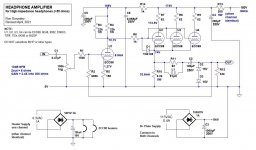
The B+ is 180V, made from full-wave rectifying the 120V secondary of an isolation transformer rated for 0.4A. The higher than expected voltage results from drawing only 170mA or so total plate current through the transformer.
1) I replaced the output cap from 470uF 100V to 100uF 400V. I figured having a 100V rated output cap was just asking for trouble, even though the voltage at the cathodes is about 75V. Still, what is it at power on? Probably up near 200V for a few seconds. Yikes. Now there's no drama.
2) Added opposite-polarity 15V zener diodes across the output, to keep giant voltage spikes from blasting downstream from the outputs. Adding them did not change the sound one bit.
3) To try to keep oscillations in check, I added an 82 ohm build out resistor. Then to keep output impedance down as low as possible, I bypassed the build out resistor with a 91uH choke (it's all I had off the shelf). Adding those didn't seem to change the sound one bit (much to my surprise).
4) The big change was adding 13dB of plate-to-grid negative feedback. By my calculations, three 6DJ8 triodes running as cathode followers with 11mA plate current each should result in about 30mA gm total. That would mean the output impedance would be about 33 ohms. As predicted, this amp sounded awful into 32 or 50 ohm headphones. Weak, like it was wheezing trying to drive them.
13dB NFB should reduce the output impedance from 33 ohms open loop (with no build out resistor) to around 8 ohms. The gain was reduced from 12X open loop to 3X closed loop (as predicted). And, as predicted, the amp is now able to drive 32 ohm headphones to acceptable levels without sounding completely stressed out, and actually sounds quite good driving my pair of Audio Technica ATH-30X headphones (70 ohms DCR). It sounds really good driving my pair of Sennheiser HD650.
5) The heater supplies are stupid, but it seems I got away with it. The amp does not hum, but the heater voltage is a bit low at 5.9V DC. I'm too lazy to try replacing the diode bridges with Schottky diodes. It seems to be OK the way it is.
Attached is a schematic of the amp. Does anyone see any horrible gaffs?
--
Attachments
Last edited:
It does open loop, especially into low impedance headphones. But the NFB puts it back.
Also, C1 rolls off low frequencies below 20Hz so that U1 doesn't try to drive subsonic frequencies present at the input but not present at the output through the feedback loop, to try to 'put them back'.
I don't notice lack of bass at all, so I think it worked. I need to get my signal generator and silly-scope hooked up so I can do actual measurements... 😱
Only one issue - power supply vripple or more importantly spike noise many cause lout headphone noise.
The large cap on the heaters may see a large inrush but I assume that the low resistance of the tube heater doesn’t I’ve then too much juice to start with?
Parallel tubes doesn’t allow tuning for each tube but that just complicates it!
Use of a b+ b- would provide some power supply noise cancellation. It could help stop loud mains noise getting to the headphones.
The ec88 is 65u, the ecc99 is substantially less so switching you'd sacrifice gain for the feedback loop in favour of current. My plan of a low mu 12BH7A + ecc99 is decent but adding feedback it does hurt.
Larger cap, just check the behaviour for larger DC spikes unplugging and plugging in headphones. It can also cause a change in the maximum current across the valves but you have resistors so that's unlikely to cause a problem. 2200uF output cap for very low rolloff with high current is also $$$ unless you go bi-polar electrolytics.
Larger cap, just check the behaviour for larger DC spikes unplugging and plugging in headphones. It can also cause a change in the maximum current across the valves but you have resistors so that's unlikely to cause a problem. 2200uF output cap for very low rolloff with high current is also $$$ unless you go bi-polar electrolytics.
Not much to improve that I could see.
- You could replace r10 by a CCS but that means solid state...
- You could run the output stage with a bit more current but that wouldn't do much in practice.
- You also might want having 3x R6, soldered right to each grid pins.
My only question would be : do you really need R7-8-9 ?
- You could replace r10 by a CCS but that means solid state...
- You could run the output stage with a bit more current but that wouldn't do much in practice.
- You also might want having 3x R6, soldered right to each grid pins.
My only question would be : do you really need R7-8-9 ?
You could add some power supply hum nulling (aka. Aikido mojo), and bypass R5 to get more loop gain, but otherwise it looks fair.
(I agree you don't need R7-8-9)
(I agree you don't need R7-8-9)
Last edited:
From your description, I think is more related to lack of current. I am guessing max 12 mW output into 32R and 20mW into 50R...with some distortion. Lower impedance headphones are often less efficient and/or difficult load (but not all of them). If cannot deliver enough current even Zout=0 cannot do much, hence Zout is not the priority. Once it starts clipping any feedback cannot do anything, often it actually makes it worse. So you have to accept lower level with those less efficient/more difficult to drive headphones.
The caveat I want to express is: if you are going to use feedback make sure you never drive the amp close or at its limit. That usually works fine.
The caveat I want to express is: if you are going to use feedback make sure you never drive the amp close or at its limit. That usually works fine.
Last edited:
R7,8,9 could be better employed in the cathodes. You might really want to take feedback from before the output inductor, but after the output capacitor, so swap those. Pretty easy to do.
Personally, I'd give the first stage more anode voltage and the second stage a larger common cathode resistor, but it probably doesn't matter much trying to drive a soft dead short (headphone). Arf! Looks good!
All good fortune,
Chris
Personally, I'd give the first stage more anode voltage and the second stage a larger common cathode resistor, but it probably doesn't matter much trying to drive a soft dead short (headphone). Arf! Looks good!
All good fortune,
Chris
First, it's a relief that no-one sees a horrible gaff, so thanks to all for giving this a once-over.
Thanks. I'll take it!
In LTspice, 100uF into 32 ohms seems to yield a low enough open loop F3 that the feedback loop can boost the bass back up to flat once the loop is closed. Open loop, 100uF is fine for 300 ohm headphones but would be no good with 50 ohm headphones. Adding the 0.47uF cap at the input before the 100k volume control (and feedback loop) rolls off the very low frequencies so they never make it to the feedback loop, which keeps U1 from overloading on subsonic junk with the loop closed. The amp seems to be working well, so I'm going with it. I should definitely get my signal generator and oscilloscope hooked up so I can measure the frequency response properly.
1) I'll have to put the output on a 'scope to see if there's rectifier switching noise. Listening tests do not reveal that, and the owner has never complained of it. The amp does not hum at all, so I think I somehow managed to deal with ripple well enough. There are no loud crackles or bangs on power up/down. Well, that did happen once, but it was because of a failing 6DJ8. The problem disappeared with a new tube in place. Tubes will be tubes.
2) One advantage of R7-8-9 is that I can read the voltage drop across them and see if one triode is drawing way more/less current than the others. I'm OK with a small mismatch.
3) Agreed; the heater supplies are stupid. I could actually make them AC and they'd be fine. Headphone amps have so little gain that AC heater wiring is not a problem if done correctly. But you know, I'd have to remove all the signal wiring to get to the heater wiring, which would be a major pain. Once I did that it would be time for a complete redesign and rebuild. I'm too lazy...
4) In this particular amp the B+ ended up being 180V. If I split that in half, I'd have +90V/-90V. I could then use larger value 160V rated capacitors for better filtering, but that would require a pretty good amount of rewiring. I'm too lazy.
Of course I could always use solid-state devices to enhance the B+ supply. A 180V 200mA capacitance multiplier on a little perfboard wouldn't be that bad of an addition. (Cap multiplier because I'd need to minimize voltage drop.) Something to think about. The biggest issue would be making it fit.
A CCS instead of R10 (cathode load resistor) would be great, but there's no room for it inside the chassis (due to my rat's nest P2P layout job, which I would change for sure!). A solid-state device there would be fine with me. Preferable, actually.
More current in the output stage would require a higher B+, since the grid bias on the cathode followers is -1.9V. I wouldn't want to run the cathode followers with grid current. For more current I'd go to a higher B+ and use 6N6P, ECC99, or 5687) instead of 6DJ8. 6N6P, ECC99, 5687 would require a lot more heater power too.
Perhaps I could put a 22k or 15k resistor in parallel with R10 to drop its value and increase the current through the cathode followers. R10 is easy to reach, fortunately.
Re: R6 (grid stopper on the cathode followers) -
I don't remember where I read it (and it would have been in a book, not a forum post!), but it was posited that individual grid stoppers were not necessary when paralleling tubes. One shared grid stopper should suffice. Why I didn't do that for R6-7-8 is a mystery(!), but probably as a way to measure plate current for each triode. Also, I don't want to burrow in there and change this, due to the messy 3D P2P layout.
Re: R7-8-9 -
This amp was based on a schematic posted by J. Broskie back in the late 1990s, which included those plate stopper resistors. I did a 'monkey see, monkey do' with that. It would be too much of a pain to get in there and remove them because the resistors are soldered right to the tube socket pins with heat shrink around them. They don't seem to hurt, so I guess they stay.
Admittedly, it's a low power amp. It was designed to drive Sennheiser HD580, which has 300 ohm impedance.
I've done my listening tests with Sennheiser HD650 (also 300 ohms), Audio Technica ATH-M30 (70 ohms), Fostex T50RP (60 ohms), and Sony MDR-7506 (60 ohms). The amp works quite well for the 300 ohm Sennheisers (sensitivity about 100dB for 1mW). It also works well for the Audio Technica and Sony, but doesn't have enough gain/drive for the Fostex. That makes sense, because the AT and Sony are quite sensitive (ATH-M30 = 102dB for 1mW, MDR-7506 = 106dB for 1mW), while the Fostex is quite a bit less sensitive (T50RP = 94dB for 1mW, which is -12dB from the MDR-7506).
If the sensitivity of a 32 ohm headphone is 100dB SPL for 1mW, then 8mW should get you to 109dB, with about 4mW headroom left over. You need louder? For the intended home entertainment use, I really don't. Or maybe that's too close to the limit for decent sound at higher volume. That could be. Good thing the intended user has relatively sensitive 300 ohm headphones and understands that this amp is not meant for low impedance cans.
The problem with doing that is that there's 75V DC before the output inductor, so another capacitor would be required. I could do that, but it would be difficult to fit a physically large, 0.47uF 250V rated film cap there. A 1uF 250V electrolytic would certainly fit (they're tiny), but that's yet another electrolytic in the signal path. What's the reasoning for moving the feedback tap?
--
Thanks again, everybody.
it looks fair.
Thanks. I'll take it!
Larger cap, just check the behaviour for larger DC spikes unplugging and plugging in headphones. It can also cause a change in the maximum current across the valves but you have resistors so that's unlikely to cause a problem. 2200uF output cap for very low rolloff with high current is also $$$ unless you go bi-polar electrolytics.
In LTspice, 100uF into 32 ohms seems to yield a low enough open loop F3 that the feedback loop can boost the bass back up to flat once the loop is closed. Open loop, 100uF is fine for 300 ohm headphones but would be no good with 50 ohm headphones. Adding the 0.47uF cap at the input before the 100k volume control (and feedback loop) rolls off the very low frequencies so they never make it to the feedback loop, which keeps U1 from overloading on subsonic junk with the loop closed. The amp seems to be working well, so I'm going with it. I should definitely get my signal generator and oscilloscope hooked up so I can measure the frequency response properly.
Only one issue - power supply vripple or more importantly spike noise many cause lout headphone noise.
The large cap on the heaters may see a large inrush but I assume that the low resistance of the tube heater doesn’t I’ve then too much juice to start with?
Parallel tubes doesn’t allow tuning for each tube but that just complicates it!
Use of a b+ b- would provide some power supply noise cancellation. It could help stop loud mains noise getting to the headphones.
1) I'll have to put the output on a 'scope to see if there's rectifier switching noise. Listening tests do not reveal that, and the owner has never complained of it. The amp does not hum at all, so I think I somehow managed to deal with ripple well enough. There are no loud crackles or bangs on power up/down. Well, that did happen once, but it was because of a failing 6DJ8. The problem disappeared with a new tube in place. Tubes will be tubes.
2) One advantage of R7-8-9 is that I can read the voltage drop across them and see if one triode is drawing way more/less current than the others. I'm OK with a small mismatch.
3) Agreed; the heater supplies are stupid. I could actually make them AC and they'd be fine. Headphone amps have so little gain that AC heater wiring is not a problem if done correctly. But you know, I'd have to remove all the signal wiring to get to the heater wiring, which would be a major pain. Once I did that it would be time for a complete redesign and rebuild. I'm too lazy...
4) In this particular amp the B+ ended up being 180V. If I split that in half, I'd have +90V/-90V. I could then use larger value 160V rated capacitors for better filtering, but that would require a pretty good amount of rewiring. I'm too lazy.
Of course I could always use solid-state devices to enhance the B+ supply. A 180V 200mA capacitance multiplier on a little perfboard wouldn't be that bad of an addition. (Cap multiplier because I'd need to minimize voltage drop.) Something to think about. The biggest issue would be making it fit.
Not much to improve that I could see.
- You could replace r10 by a CCS but that means solid state...
- You could run the output stage with a bit more current but that wouldn't do much in practice.
- You also might want having 3x R6, soldered right to each grid pins.
My only question would be : do you really need R7-8-9 ?
A CCS instead of R10 (cathode load resistor) would be great, but there's no room for it inside the chassis (due to my rat's nest P2P layout job, which I would change for sure!). A solid-state device there would be fine with me. Preferable, actually.
More current in the output stage would require a higher B+, since the grid bias on the cathode followers is -1.9V. I wouldn't want to run the cathode followers with grid current. For more current I'd go to a higher B+ and use 6N6P, ECC99, or 5687) instead of 6DJ8. 6N6P, ECC99, 5687 would require a lot more heater power too.
Perhaps I could put a 22k or 15k resistor in parallel with R10 to drop its value and increase the current through the cathode followers. R10 is easy to reach, fortunately.
Re: R6 (grid stopper on the cathode followers) -
I don't remember where I read it (and it would have been in a book, not a forum post!), but it was posited that individual grid stoppers were not necessary when paralleling tubes. One shared grid stopper should suffice. Why I didn't do that for R6-7-8 is a mystery(!), but probably as a way to measure plate current for each triode. Also, I don't want to burrow in there and change this, due to the messy 3D P2P layout.
Re: R7-8-9 -
This amp was based on a schematic posted by J. Broskie back in the late 1990s, which included those plate stopper resistors. I did a 'monkey see, monkey do' with that. It would be too much of a pain to get in there and remove them because the resistors are soldered right to the tube socket pins with heat shrink around them. They don't seem to hurt, so I guess they stay.
From your description, I think is more related to lack of current. I am guessing max 12 mW output into 32R and 20mW into 50R...with some distortion. Lower impedance headphones are often less efficient and/or difficult load (but not all of them). If cannot deliver enough current even Zout=0 cannot do much, hence Zout is not the priority. Once it starts clipping any feedback cannot do anything, often it actually makes it worse. So you have to accept lower level with those less efficient/more difficult to drive headphones.
The caveat I want to express is: if you are going to use feedback make sure you never drive the amp close or at its limit. That usually works fine.
Admittedly, it's a low power amp. It was designed to drive Sennheiser HD580, which has 300 ohm impedance.
I've done my listening tests with Sennheiser HD650 (also 300 ohms), Audio Technica ATH-M30 (70 ohms), Fostex T50RP (60 ohms), and Sony MDR-7506 (60 ohms). The amp works quite well for the 300 ohm Sennheisers (sensitivity about 100dB for 1mW). It also works well for the Audio Technica and Sony, but doesn't have enough gain/drive for the Fostex. That makes sense, because the AT and Sony are quite sensitive (ATH-M30 = 102dB for 1mW, MDR-7506 = 106dB for 1mW), while the Fostex is quite a bit less sensitive (T50RP = 94dB for 1mW, which is -12dB from the MDR-7506).
If the sensitivity of a 32 ohm headphone is 100dB SPL for 1mW, then 8mW should get you to 109dB, with about 4mW headroom left over. You need louder? For the intended home entertainment use, I really don't. Or maybe that's too close to the limit for decent sound at higher volume. That could be. Good thing the intended user has relatively sensitive 300 ohm headphones and understands that this amp is not meant for low impedance cans.
You might really want to take feedback from before the output inductor, but after the output capacitor, so swap those.
The problem with doing that is that there's 75V DC before the output inductor, so another capacitor would be required. I could do that, but it would be difficult to fit a physically large, 0.47uF 250V rated film cap there. A 1uF 250V electrolytic would certainly fit (they're tiny), but that's yet another electrolytic in the signal path. What's the reasoning for moving the feedback tap?
--
Thanks again, everybody.
Last edited:
If you do go AC careful on the first stage. If you share the transformer with the HT the rectifier buzz gets onto the heater supply and it does not take much pF to the first grid to get it into the input. If you are stereo and building from scratch then the first ECC88 could do both L and R and you could run that just on DC. It also means you could swap it for something with more gain and get more FB.
Last edited:
Thanks, that's a good point. In this case, there are two separate 6.3V AC transformers, one for each channel's worth of 6DJ8 tubes. That's probably why my stupid simple DC supplies are working without undue noise, since the heaters are completely separate transformers from the B+ supply. That's just dumb luck, because back when I first built this thing I had no clue about interwinding capacitance and leakage inductance causing diode switching noise transfer across windings. Just plain dumb luck. 🙂
If I were to start over, I'd use a separate voltage amp tube, probably a 12AX7, and three or four 6N6P triodes in parallel for the cathode follower output stage. Or better yet, artosalo posted a really good 6N6P White Cathode Follower with DC coupled input voltage amp design that I'd like to try.
But this amp was built around 20 years ago, and I don't want to rip its guts out and start over.
--
Last edited:
You might really want to take feedback from before the output inductor, but after the output capacitor, so swap those. Pretty easy to do.
It took me a minute, but it finally dawned on me that this would be pretty easy to implement. Like in the attached schematic, add C7 from the cathodes of the output followers, in series with R2 (the NFB parallel resistor).
I think 0.22uF would be enough C for C7, as long as I'm correct that the F3 is defined by the time constant of C7 and R2, and not C7 and R1. But I could be wrong about that...
--
Attachments

Last edited:
Actually, if I want the NFB to correct for the low frequency roll-off caused by C2 into a low impedance load, then I do want the feedback loop to connect from the negative side of C2 (the output of the amp, after the output coupling cap).
What would be the problem with doing that?
--
What would be the problem with doing that?
--
That should be ok. Short C7 and resize the output coupling capacitor C2 so you get a LF corner
of around 2Hz with the feedback, and the smallest (50R) load used, both connected.
of around 2Hz with the feedback, and the smallest (50R) load used, both connected.
Last edited:
I'm sorry I wasn't clearer earlier. What was meant was to physically swap the output capacitor and the output inductor. Feedback would still come from the downstream (no DC) side of the cap, but upstream of the output inductor. That inductor is something you probably don't want in the feedback loop, but you definitely *do* want the cap.
I'd also reconsider leaving much signal voltage across that cap. Electrolytics with a good DC bias aren't nearly as evil as legend has it, but minimizing the signal voltage across any capacitor minimizes distortion, and capacitors are cheap these days. Bigger is better in this respect. Flatter open-loop response also allows for more feedback correction at lower frequencies. Food for thought, anyway.
All good fortune,
Chris
Thanks. I hadn't thought of moving the R11 and the inductor there because I thought the idea was to have the build out resistor (R11) connected directly to the cathodes of U2-3-4, as a 'stopper'. Will that build out resistor still do its job of suppressing oscillations into a capacitive load if it's over on the other side of C2?
Re: Value of C2 output capacitor:
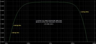
I modeled the open loop frequency response in LTspice, into a 50 ohm load. It says bass response should only be down -2.0dB at 20Hz, -3dB at 16Hz.
Into a 32 ohm load, it's -4.1dB at 20Hz, -3dB at 25Hz.
Into a 300 ohm load, it's -0.4dB at 20Hz.
I think those are low enough. No?
(Bear in mind that there is a 0.47uF cap at the input, which with the 100k volume control makes -3dB @ 3.5Hz. Maybe that cap should be changed to 0.22uF to put the input filter F3 at 7.2Hz...)
I wasn't able to safely mount a physically larger capacitor for C2 due to my dumb layout. I might be able to put a second cap in parallel with C2, but it will have to be 'flying' (which might be physically unstable), or it will have to be mounted somewhere far away from C2 and connected with a couple inches of hookup wire. The idea of the output signal running through a few inches of wire over the rest of the circuit bothers me, and I don't want to rip apart the whole thing to re-do the layout. The thing is working and sounds good, after all.
Also, what about capacitor quality? I have some 200uF 300V photo-flash capacitors that have always worked out well for PSU duty and are physically small enough to fit. The 100uF 400V cap I chose for C2 is a high quality Nichicon 105deg part. If I parallel the two I'll have 300uF. But will the photo-flash cap be a liability? (I think probably yes.)
--
PS - Re: that inductor -
According to an LR filter calculator I found online, the output impedance of 82R in parallel with 91uH is about 4 ohms at 1kHz, 11 ohms at 20kHz. It does rise with frequency since the inductance is a bit higher than optimal, but it's still nice and low. Is that really a problem for the input 6DJ8 driving the NFB loop?
Re: Value of C2 output capacitor:
I modeled the open loop frequency response in LTspice, into a 50 ohm load. It says bass response should only be down -2.0dB at 20Hz, -3dB at 16Hz.
Into a 32 ohm load, it's -4.1dB at 20Hz, -3dB at 25Hz.
Into a 300 ohm load, it's -0.4dB at 20Hz.
I think those are low enough. No?
(Bear in mind that there is a 0.47uF cap at the input, which with the 100k volume control makes -3dB @ 3.5Hz. Maybe that cap should be changed to 0.22uF to put the input filter F3 at 7.2Hz...)
I wasn't able to safely mount a physically larger capacitor for C2 due to my dumb layout. I might be able to put a second cap in parallel with C2, but it will have to be 'flying' (which might be physically unstable), or it will have to be mounted somewhere far away from C2 and connected with a couple inches of hookup wire. The idea of the output signal running through a few inches of wire over the rest of the circuit bothers me, and I don't want to rip apart the whole thing to re-do the layout. The thing is working and sounds good, after all.
Also, what about capacitor quality? I have some 200uF 300V photo-flash capacitors that have always worked out well for PSU duty and are physically small enough to fit. The 100uF 400V cap I chose for C2 is a high quality Nichicon 105deg part. If I parallel the two I'll have 300uF. But will the photo-flash cap be a liability? (I think probably yes.)
--
PS - Re: that inductor -
According to an LR filter calculator I found online, the output impedance of 82R in parallel with 91uH is about 4 ohms at 1kHz, 11 ohms at 20kHz. It does rise with frequency since the inductance is a bit higher than optimal, but it's still nice and low. Is that really a problem for the input 6DJ8 driving the NFB loop?
Attachments
Last edited:
resize the output coupling capacitor C2 so you get a LF corner of around 2Hz with the feedback, and the smallest (50R) load used, both connected.
According to simulations...
The closest standard value would be 360uF, so I think 330uF or 390uF would meet that requirement.
With C2 = 100uF, closed loop, the low frequency F3 is about 6.5Hz. Is that really so bad?
With C1, the 0.47uF input filter cap in place, the closed loop F3 is about 10Hz, down -1dB at 20Hz (which is fine with me).
If I change C1 to 0.22uF, the F3 is now 14.5Hz, and it's down -1.7dB at 20Hz closed loop (still OK by me).
Bandwidth limiting the input of a feedback amplifier is another way to keep things under control. The tactic works well for power amplifiers with NFB for speakers, and what is a headphone amp after all?
--
Thanks. I hadn't thought of moving the R11 and the inductor there because I thought the idea was to have the build out resistor (R11) connected directly to the cathodes of U2-3-4, as a 'stopper'. Will that build out resistor still do its job of suppressing oscillations into a capacitive load if it's over on the other side of C2?
Re: Value of C2 output capacitor:
I modeled the open loop frequency response in LTspice, into a 50 ohm load. It says bass response should only be down -2.0dB at 20Hz, -3dB at 16Hz.
PS - Re: that inductor -
According to an LR filter calculator I found online, the output impedance of 82R in parallel with 91uH is about 4 ohms at 1kHz, 11 ohms at 20kHz. It does rise with frequency since the inductance is a bit higher than optimal, but it's still nice and low. Is that really a problem for the input 6DJ8 driving the NFB loop?
The output cap's value isn't any giant deal, just trimming on the cake. What you have is working fine, so you don't have much payback for changing it. If you were starting fresh, you'd get a different return for your effort ratio.
The output inductor is a trickier question. I wouldn't say that the input 6DJ8 drives the feedback loop to any significant extent, but being inside the feedback loop negates some of the inductor's function. Amplifier outputs with feedback taken from their output nodes have a falling response with frequency (above a certain point), so are "inductive". This inductiveness tries to resonate with the various capacitances of the outside world and load, so the purpose of the output inductor is to try to isolate the fedback amplifier from the cruel world outside its feedback loop.
WRT its function as a cathode stop: yes, it contributes. But a better solution is to move R7,8,9 to the cathodes. I know you don't want to, but you'll also get some help current sharing, so there's that. Good fortune however you choose,
Chris
- Home
- Amplifiers
- Tubes / Valves
- OK, criticize my OTL Headphone Amp please