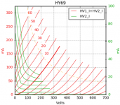
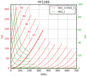
Them are some nice curves there L-G. I did not expect them to look so nice, but it is hardly surprising that they work well.
Douglas
Douglas
Thanks for the triode curves, very nice looking. It is a great help for me. Waiting for the A2 curves.
I think 380 volt (anode to cathode) @40ma is safe for A1--please confirm.
Regards
I think 380 volt (anode to cathode) @40ma is safe for A1--please confirm.
Regards
Apologies, I should have realized it sooner, but I will not be able to trace A2 curves, it is a limitation of the tracer. A2 for true triodes is viable, there are two positive HV supplies, one must be used for the grid to trace A2. For triode-strapped pentodes, both HV supplies are in use for plate and screen, so it cannot be done.
Apologies, I should have realized it sooner, but I will not be able to trace A2 curves, it is a limitation of the tracer. A2 for true triodes is viable, there are two positive HV supplies, one must be used for the grid to trace A2. For triode-strapped pentodes, both HV supplies are in use for plate and screen, so it cannot be done.
Really? How does the machine tell a triode from a pentode rigged as triode at the socket?
minhaj, what load? Whilst looking at DHP tubes, the datasheet for 4E27 says 30W from a single tube at 750V B+( I think ). There is the issue of delivering 7.5A/5V to light its cathode. 75W plate... 🙂
Am going to suggest 5k. I have run these at 30% U-L to a 10k a-a output( the Peerless S265Q )at 350V.
cheers,
Douglas
Last edited:
Nice job!
I did get in the ballpark while estimating the operative conditions. For 400/40-45 mA the bias is 40-45 V range indeed.
I did get in the ballpark while estimating the operative conditions. For 400/40-45 mA the bias is 40-45 V range indeed.
Now it's time to buy few HY69 and import to my country. I think socket and plate cap is same as 807. It will take some time due to covid19 situation. Anyways, once HY69 reaches my door I will modify my 300B SE and give you update about their sonic qualities.
Regards
Regards
minhaj - yes, it is the same plate cap as the 807.
This is off topic, but the HY69 A2 curves remind me of some other A2 curves I am very close to at the moment, the 801A.
I have been developing a 801A A2 amplifier for several months, it is getting very close to completion. It needs one last breadboard before the circuit is final.
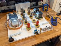
I thought to myself, well if I am going to take the time to breadboard, I might as well make something I can re-use - so I made a prototyping board on plywood, completed this morning.
All the pieces are now in place, including custom iron from Sowter, I should have the circuit functional by the weekend, very exciting 😀
It goes EF37A > 6BX7 parallel CF > direct-coupled 801A at near 0Vg1 bias with plate to EF37A cathode feedback. When it is done done, I'll make a thread with measurements and photos. It will be 6-7W into 8ohms.

Last edited:
And then, if you want to get totally NUTS, try an 813 with g2-as-anode. No need for a plate cap and exposed HV. 20W of dissipation. 50W of cathode power to light it though...LOL
Douglas
Douglas
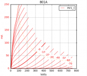
I don't have the data handy to overlay them without retracing, but here are the full 801A curves for comparison. They follow the RCA datasheet very well, this one was made by Taylor.
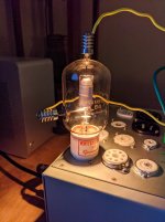
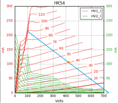
Thanks for the idea, that's a good one, but I am already going a little nuts - my next design is based on the HK54 transmitting triode 😀 15W single-ended design, will spend most of its time in A2 with +38V grid bias point, drawing around 10mA at idle and 60mA at peak swing, 25W filament.
3K load line, 425V 105mA bias, will require NFB of course.

Thanks for the idea, that's a good one, but I am already going a little nuts - my next design is based on the HK54 transmitting triode 😀 15W single-ended design, will spend most of its time in A2 with +38V grid bias point, drawing around 10mA at idle and 60mA at peak swing, 25W filament.

3K load line, 425V 105mA bias, will require NFB of course.

Last edited:
Is a low voltage 845 amp a possibility? There is some old chatter about them here in old threads. New 845s are way cheaper than 300bs, and 4 watts with a 5k OPT seems pretty do-able ....
Paul
Paul
I am running a low power 845 amp as my daily driver. They are Psvanes bought cheaply on Amazon. I have about 9 volts on the filament. About 400 volts on the plate and a 6K load. The 845 amp drives horns so I am using DC on the filaments. I have used it for about five years like this. Worth doing if you find 845s cheaper than 300Bs. I am about to likely replace the amplifier with something else and reconfigure for 20 watts instead to drive lower efficiency speakers.
I am looking to configure two competing systems to see who can win. Sort of a medium efficiency versus high.
I am looking to configure two competing systems to see who can win. Sort of a medium efficiency versus high.
- Home
- Amplifiers
- Tubes / Valves
- SE Amp with Thoriated Tungsten output tube
