And it could change from recording to recording.
dave
Dave,
funny thing I was just thinking of you.
From time to time I am silently lurking in the widerange forum, and now having managed to score one of the V-fet amps, I'll need to head over there more often, my 88dB 2-way (4Ohm) will probably not be the best match... but I knew that beforehand.
Cheers,
Max
Congrats Max. If teh ACA and the SIT-3 are an good reference this should be a very good amplifier. WHat are your 2-ways, the sensitivity would be fine at lower levels, it is onlt a question of what the impedance looks like.
I wil get one in Round 3, some kind member is donating VFETs so the few mods who have been waiting pateiently can get one if they want.
dave
I wil get one in Round 3, some kind member is donating VFETs so the few mods who have been waiting pateiently can get one if they want.
dave
the impression commonly shared was that positive phase harmonics is more "right in your face" and more in front of the speakers, whereas negative phase distortion is more lush and makes soundstage deeper.
A impression i share,
st.
A impression i share,
st.
Dave,
let me dig that info up, I'll post it in the speaker forum, don't really want to get this thread too much polluted with my "problems".
Your input is higly appreciated,
Cheers,
Max
EDIT: That's a very kind gesture from this member, you all deserve it without any doubt!
let me dig that info up, I'll post it in the speaker forum, don't really want to get this thread too much polluted with my "problems".
Your input is higly appreciated,
Cheers,
Max
EDIT: That's a very kind gesture from this member, you all deserve it without any doubt!
Last edited:
I am coming in a bit late , but It looks to be the perfect amp for the HF section of my HPD 385 , LF driven by the F6 , what do you guys think 🙂
.
.
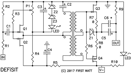
Since the VFET amp makes it easy to try both phases of second harmonic distortion ("H2"), try them both and discover which you like more.
Negative Phase H2: build the amp exactly as Nelson's schematics show
Positive Phase H2: swap the transformer output wires AND swap the loudspeaker terminals
Which do you prefer? Or perhaps (a) which do you prefer for LF and also (b) which do you prefer for HF?
Negative Phase H2: build the amp exactly as Nelson's schematics show
Positive Phase H2: swap the transformer output wires AND swap the loudspeaker terminals
Which do you prefer? Or perhaps (a) which do you prefer for LF and also (b) which do you prefer for HF?
It may not be a matter of what I prefer or not prefer first , some "stuff" are "made" to play together in first place , reading the first page lead me to believe ( wrongly ?? ) that this new amp will perform very well in HF transducers , like the HPD 385 ones , what ever happens I have the needed parts so it's a matter of "time" to know 😀
.
.
Here's a brief amp question that probably belongs in a different thread. If it does, could someone kindly point me to the right place to post?
Question: How hot does this amp run? How would it compare, for example, to a stereo configured ACA, or to a 300B amp like the Sun Audio SV-300BE or Audio Note Kit One?
I have those various amps and am trying to get an idea of where this might need to live in my fairly space limited setup (concerning the need for ventilation).
TIA
@ KT, right thread is here: DIY Sony VFET pt 1
And all info is in the first post from Nelson Pass (the attachment)
It will run/dissipate 57Watts per channel
And all info is in the first post from Nelson Pass (the attachment)
It will run/dissipate 57Watts per channel
or you can put a nice small film cap output and have a wondefull toy for tweeter or horn ..
so happy the frenchy 🙂
I get why the VFET is so coveted amongst many great audio engineers. I also understand why to keep the cost down only one is used in this offering. However, will not placing such a large electrolytic capacitor in the output signal path negatively offset some linearity this transistor is known for? Again, I'm assuming this is to keep costs down, as designing a push pull class A version using these devices would easily triple the cost.
Not looking to start a debate, Just wanting to get some feedback from the group regarding this.
What a pearl of wisdom. Reminds me of the patient/doctor joke P: doctor it hurts when I do this. D: dont do that then'...
I get why the VFET is so coveted amongst many great audio engineers. I also understand why to keep the cost down only one is used in this offering. However, will not placing such a large electrolytic capacitor in the output signal path negatively offset some linearity this transistor is known for? Again, I'm assuming this is to keep costs down, as designing a push pull class A version using these devices would easily triple the cost.
Not looking to start a debate, Just wanting to get some feedback from the group regarding this.
The First Watt SIT-3 has a big honkin' capacitance on its output. It was a commercial success in the super picky audiophile market. It also has a capacitor on its input.
I get why the VFET is so coveted amongst many great audio engineers. I also understand why to keep the cost down only one is used in this offering. However, will not placing such a large electrolytic capacitor in the output signal path negatively offset some linearity this transistor is known for? Again, I'm assuming this is to keep costs down, as designing a push pull class A version using these devices would easily triple the cost.
Not looking to start a debate, Just wanting to get some feedback from the group regarding this.
I think that was the reason to bypass C1 with C5 : to alleviate the negatives effects of such a large capacitor in the signal path. But to my understanding, the fact that this design do not incorporate negative feedback or degeneration (and an output transformers) far outshaddow this limitation.
Of course, nobody who is lucky enough to win the buyer's lottery and obtain one of these amps, would ever think about changing any aspect of Nelson's design. You use his circuits, his boards, his specified part-numbers, and you even wire the chassis using the same colors of insulated wire as he drew on page 11 of the pdf manual. When Picasso says "paint this Cadmium Yellow," you don't argue, you go buy Cadmium Yellow paint and you follow his instructions.
However, after those approx. 200 amp kits are sold and built and installed, the post-VFET versions will thrive and multiply. Builders with lots of chutzpah & bravery will no doubt add embellishments, accessories, and features not present in the original NP VFET design.
One such possibility, still just a prototype, is shown below. It's a four pole lowpass filter, which replaces Nelson's two pole filter shown on page 6 of the pdf manual. The goal of this PCB is to remove even greater amounts of hash, crud, noise, ick, and general HF unpleasantness from the SMPS output, providing an even cleaner DC supply to the amp. As you can see for yourself if you look up the inductor part number -- clearly visible in the stunning photographs taken by wizard 6L6 -- the components themselves are good for about 9 amperes of DC current. Each VFET channel draws less than 2 amps, and my wet-finger-in-the-breeze guess is that future non-VFET channels will draw less than 3 or 3.5 amps. So there's a nice margin of safety. When you order PCBs from fab, should you specify double-thick (2 oz) copper? Oh yes.
I'm still testing the board and performing experiments. It may not pass the tests, the experiments may fail, and this board may never get released. But, fingers crossed, so far so good.
The top side silkscreen says "6A maximum" because I've provided flexible PCB footprints that accommodate several different inductor part-numbers. Expecting the inevitable backorder / out of stock / we don't have Mouser in my country / kinds of difficulties. The highest current inductor that fits, is rated 9.8 amperes. The substitutes that fit, have lower current ratings, including one rated for "only" 6A. The top silkscreen makes the conservative worst-case assumption that the builder has been forced to purchase the scrawniest inductor.
_
This is question wrt to inductors that confuses me: isn't the inductance varying as a function of current? If you use a 9A part at 3.5A current wouldn't you get about 1/3 of the rated inductance on the part and consequently need to adjust the values accordingly? 24 uH at rated 56 uH at 1KHz... what frequency do we need to filter? I guess the inductance will be higher at the higher freq as well.
Last edited:
transferfunction, don't forget there are already push-pull projects
using these Sony vfets:
https://firstwatt.com/pdf/art_sony_vfet_pt1.pdf
https://firstwatt.com/pdf/art_sony_vfet_pt2.pdf
https://firstwatt.com/pdf/art_diy_sony_vfet.pdf
using these Sony vfets:
https://firstwatt.com/pdf/art_sony_vfet_pt1.pdf
https://firstwatt.com/pdf/art_sony_vfet_pt2.pdf
https://firstwatt.com/pdf/art_diy_sony_vfet.pdf
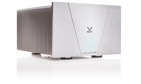
I love that amplifier. The only one i have that really comes close has output transformers.
It is all about execution and trade-offs. With round 4 you will be able to do (at least i would be very surprised to not see someone come up with one) an X-variation which should allow for no output caps.
I consider this amplifier to be the coveted “limited” Lauch Edition. Watch it evolve over the next years. That is as exicting as this lottery is now.
The forum has already been practising on the base supplied by Nelson’s ACA. How far has that 5w "around the picnic table” amplifier evolved to get to AVA 1.8, ACA with Premium Parts, Tony’s Kampala? Bridged, parallel, stereo… Parallel bridged?
That seems pretty well the path for these too. But a starting point with much less care to keeping it cheap, and a growing number of front ends.
Anyone already working on a tube front end yet?
Each output channel could be used much like an OTL tube. But one can flip phase unlike tube stages. Put your thinking caps on (i am sure there are already those scheming in the background).
dave
- Home
- Amplifiers
- Pass Labs
- DIY Sony VFET pt 1