Get the F6 built and working first with no added boards or gizmos...
Then, and only then, add the cool switch and speaker protection thingys.
Then, and only then, add the cool switch and speaker protection thingys.
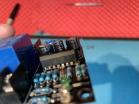
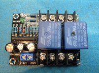
As ZM mentioned, is it a 12V board? Check the SIL chip nbr on the board. Is it a UPC1237 ? This is originally a chip from NEC, but out of production for a long time. The current chips are Chinese knockoffs. Supply voltage for that chip is between 25 and 60V. So If this is the case, I guess the 2 relay coils are in series to get to 24V. That you can measure with your DMM.Could not locate a schematic for the generic speaker protection board (12vdc, 50-60mA). Attached is a close-up. The other board is a 120vac to 12vdc step down rated at 2A (2000mA). What do you think about this as an option? Any adverse impact to sound quality?
Thanks.
I got some quantity of uPc1237 directly from Pras - seems they behave as prescribed, so no reason to doubt
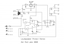
however, one of things with uPc1237 - for proper operation it needs AC rail connected, besides supply rail
that one works in for switch-off detection function, and without that, switch off of relays can't operate properly , it will lag
edit: my sch added
however, one of things with uPc1237 - for proper operation it needs AC rail connected, besides supply rail
that one works in for switch-off detection function, and without that, switch off of relays can't operate properly , it will lag
edit: my sch added
Attachments
Last edited:
I didn't think to test these pots since they came from the kit. My bad. I can't explain why the second two are 20K pots, but I won't be using them.
That's actually a bit freaky given the 4 trimmers came on a tape rail.
So the issue occurred at the factory.
BTW, W502 is 5K (50 x 10^2) and W203 is 20K (20 x 10^3). The W
indicates the combination of footprint and adjustment screw location.
So what you measured if consistent with their nominal values.
@Chiptech -
Did you only build one amp channel so far? From previous posts, I thought you built both.
Did you only build one amp channel so far? From previous posts, I thought you built both.
Get the F6 built and working first with no added boards or gizmos...
Then, and only then, add the cool switch and speaker protection thingys.
Thanks 6L6. And thank you for taking the time to document your build. That is the plan. Doing some homework while waiting on parts. Researching if and how others have implemented these mods and to what end.
As ZM mentioned, is it a 12V board? Check the SIL chip nbr on the board. Is it a UPC1237 ? This is originally a chip from NEC, but out of production for a long time. The current chips are Chinese knockoffs. Supply voltage for that chip is between 25 and 60V. So If this is the case, I guess the 2 relay coils are in series to get to 24V. That you can measure with your DMM.
More photos of board attached. The number on the chip s/b visible. This is a generic Chinese board w/no documentation. 12v is printed on the board. However the description on Amazon is as follows:
all-round protection of your expensive speaker!
The speaker protection board using UPC1237 dedicated chip design and manufacturing
instant shutdown feature
has a power-on delay and DC protection
10A relay is loose music quality
Sheet selection 1.6MM thick high-FR-4 board manufacturing tin foil sprayed
the resistance rings are gold film resistor copper feet. And with a red power indicator
indicating that green light
power relay approximately 3 seconds
the work indicator.
The protection board using a single power supply voltage AC 10V-18V
Mute delay boot
you can take a group of electric power to the amplifier board.Try to use conditional independence winding or separate power supply.
Amplifier midpoint potential protection
shutdown speed off.
12 / 24V DC
the midpoint of DC from the control point of> 0.7V.
All finished boards are good debugging
Note:
Size:6.5x5cm/2.56x1.97inch
and power test.
Please allow 1-3mm error due to manual measurement. pls make sure you do not mind before you bid
Due to the difference between different monitors
the picture may not reflect the actual color of the item. Thank you!
Package Included:
1x Protection Circuit Board
Attachments
@Chiptech -
Did you only build one amp channel so far? From previous posts, I thought you built both.
I have built only the B channel.
I had to order new pots, so while I wait for the them to arrive, I have been working my way thru this thread. More to go on it. Great stuff.
A lot to learn.
I have noted that I'm not the first person to show up whining about a burned R4 resistor.
Transformer Bracket Suggestion
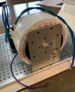
Moving mindfully on my F6, but wanted to share my solution to vertically mounting the transformer. I couldn't find a commercially produced bracket in stock anywhere.
So I went to Home Depot and bought a tie plate. Bent it into an L shape using a well-secured vise, drilled the appropriate holes in it and presto!
They have thinner gauge models that would probably also work, but I wanted the additional strength. I would caution you to drill the holes somewhere other than the area where you are building in order to avoid contamination with fine metal particles, but a good vacuuming or sweep with a magnet would probably do the trick.
Attachments
Can someone please provide the values for R7, R8, R9, and R10 with the 6.8V zener mod? Should all four be 3.3Kohm or just 7 and 8, with 9 and 10 remaining at 10Kohm? Is 1/4 watt satisfactory?
Thank you.
Thank you.
Moving mindfully on my F6, but wanted to share my solution to vertically mounting the transformer. I couldn't find a commercially produced bracket in stock anywhere.
So I went to Home Depot...
Great job with the DIY bracket. Looks nice and beefy.
Toroid corp, located in Maryland sells one here:
L-Bracket – Toroid
Best,
Anand.
Last edited:
Thanks. I saw the one from Toroid, but the size I needed says "Available on backorder". :-(
What's that they say about necessity and invention?
What's that they say about necessity and invention?


Just change R7 and R8. 1/4W is adequate.
Thank you Dennis.
PSU output voltage
Hello, I tested today the PSU and the output DC values are -26.0 V and +26.0 V.
Is it an issue as 24/25 V are standard values?
Thanks
Hello, I tested today the PSU and the output DC values are -26.0 V and +26.0 V.
Is it an issue as 24/25 V are standard values?
Thanks
Hello, I tested today the PSU and the output DC values are -26.0 V and +26.0 V.
Is it an issue as 24/25 V are standard values?
Thanks
26V is fine. Might even go down a bit to 24/25v when you put load on it (read: when you connect your amplifier boards).
- Home
- Amplifiers
- Pass Labs
- F6 Illustrated Build Guide