Hello,
I have many NPR24 hot swappable rectifiers which were used in RF communication centres. These plug into a magazine and run in parallel to provide large currents for comms gear such as paging and LTE Transmitters.
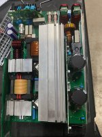
Not Audio related however, these Switching power supplies are exceptionally well built and utilise ZVS topology as well as Power factor correction to minimise interference. The control uses a Atmel Mega32L and communicates using RS-485 modbus link (I think) communicates between the SM60 supervisory controller.
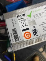
The NPR series where made back in 2007 by Powerware now bought out by Eaton.
I’ve contracted Eaton a few times regarding technical info, schematic and the modbus register map and as expected, got blown off. Can’t give information as its propitiatory line. Shame!
I feel there’s life left in these old girls and I’m finding plenty of used ones coming up on the web for not much at all. I’d like to save them from land fill or going to green waste and reverse engineering how to talk to them.
Question is, is there anyone with information about these such as register map for the modbus and schematic.
Somebody out there probably repairs them in early days.
Please PM if you can help out. Pictures attached
Cheers
I have many NPR24 hot swappable rectifiers which were used in RF communication centres. These plug into a magazine and run in parallel to provide large currents for comms gear such as paging and LTE Transmitters.
Not Audio related however, these Switching power supplies are exceptionally well built and utilise ZVS topology as well as Power factor correction to minimise interference. The control uses a Atmel Mega32L and communicates using RS-485 modbus link (I think) communicates between the SM60 supervisory controller.
The NPR series where made back in 2007 by Powerware now bought out by Eaton.
I’ve contracted Eaton a few times regarding technical info, schematic and the modbus register map and as expected, got blown off. Can’t give information as its propitiatory line. Shame!
I feel there’s life left in these old girls and I’m finding plenty of used ones coming up on the web for not much at all. I’d like to save them from land fill or going to green waste and reverse engineering how to talk to them.
Question is, is there anyone with information about these such as register map for the modbus and schematic.
Somebody out there probably repairs them in early days.
Please PM if you can help out. Pictures attached
Cheers
Attachments
Last edited:
I worked with these units several years ago. The rack that held two of them had a separate comms pcb going back to the sm60. This would fail (intermittent comms to the sm60) and I would have to replace the whole rack (time consuming).
I don't believe they repaired them, so no service manual. I might still have the installation manuals.
I know where those units came from (I recognise the asset label). Could you remove it please?
I don't believe they repaired them, so no service manual. I might still have the installation manuals.
I know where those units came from (I recognise the asset label). Could you remove it please?
Thank for the reply MR I.
I’ll get the first picture removed by the admin. Sorry about that. Didn’t cross my mind that anyone would notice an asset number..
I’d remove the picture myself however can’t now the post is > 30minutes old.
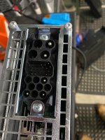
I was wanting to know the gold pins on plug. I’ve worked out 2 are for Rs-485 comms and another 2 for powering the comms isolation supply. The others 5 and what there function is I have no glue unless I can get hold of a magazine and work it out from there. Maybe ID setting or voltage sensing??
Any info would be appreciated.
Our local radio club has many of these so I’m helping out working out a good outcome for them over
seeing all of it put in electronic waste.
Just too good of a design and made for the job AND worth the pain in making these a solid radio power supply.
Do you have modbus map by any chance?
I’ll get the first picture removed by the admin. Sorry about that. Didn’t cross my mind that anyone would notice an asset number..
I’d remove the picture myself however can’t now the post is > 30minutes old.
I was wanting to know the gold pins on plug. I’ve worked out 2 are for Rs-485 comms and another 2 for powering the comms isolation supply. The others 5 and what there function is I have no glue unless I can get hold of a magazine and work it out from there. Maybe ID setting or voltage sensing??
Any info would be appreciated.
Our local radio club has many of these so I’m helping out working out a good outcome for them over
seeing all of it put in electronic waste.
Just too good of a design and made for the job AND worth the pain in making these a solid radio power supply.
Do you have modbus map by any chance?
Last edited:
I worked with these units several years ago. The rack that held two of them had a separate comms pcb going back to the sm60. This would fail (intermittent comms to the sm60) and I would have to replace the whole rack (time consuming).
I don't believe they repaired them, so no service manual. I might still have the installation manuals.
I know where those units came from (I recognise the asset label). Could you remove it please?
Picture removed by Moderator as requested.