I am interested in the variation in actual Helmholtz resonance frequency versus that which is predicted by theory.
I remember an article by Augspurger in SpeakerBuilder magazine in the 1990's, but I can't locate my copy (I thought I saved them all)...
Does anyone have data, or can point me toward some research, on the normal variation that might be expected.
Thanks !
jim
I remember an article by Augspurger in SpeakerBuilder magazine in the 1990's, but I can't locate my copy (I thought I saved them all)...
Does anyone have data, or can point me toward some research, on the normal variation that might be expected.
Thanks !
jim
When the correct pipe, boundary, end corrections and vent mach are used, the calculations are > accurate enough. With three variables though, coming up with a range is way too tedious for me, but assume a [much] more accurate enough percentage chart can be calculated than the +/- 10% for T/S specs, vent tuning I've seen published in magazines long ago.
Thanks... I am collaborating with another designer on a very large woofer cabinet. A 200 liter box tuned to 30 Hz. Once the box is built, the extensive bracing would make changing the vent length quite difficult.
In the margins of my ancient 3rd edition loudspeaker design cookbook I wrote a note to myself on the vent calculation equations: "RB says +/- 5%"... the identity of "RB" is lost to my flushed memory cells, Robert Bullock perhaps?
In our case +/- 5% variation in Fb box tuning frequency would be +/- 1.5 Hz, which simulation shows to be quite acceptable. In your opinion, would you expect the variation to be within +/- 5% for a properly constructed vent, with a proper vent calculation?
Thanks!
Last edited:
IME port end correction falls in the .65-.75 range, so if you plan box dimensions for .75, you should be fine with whatever it ends up being.
What kind of port and lining are you using?
What kind of port and lining are you using?
The current plan calls for a pair of 4" tubular ports, with flares at both ends.
We have not decided on a damping strategy yet. I imagine it will be lining the walls with a layer of foam, melamine foam would be my first choice. This is not a subwoofer, this will house a large diameter professional driver operating as high as 750 Hz.... thus it is more critical to strike the right balance between midrange absorption and bass response.
After more thought, I realize it will not be that difficult to change the port length. In fact I am hoping to tune the vents with near field measurements and impedance sweeps.
Jim
That is the best way. even better would be to checkout with prototype box how much the mid leakage is and try to tune that as well. Port location change / some damping in the port system might be needed if you are after optimal performance.
In your opinion, would you expect the variation to be within +/- 5% for a properly constructed vent, with a proper vent calculation?
Can't say as I've never thought about it since I don't generally 'think' in percentages plus early on all tuning was done 'in situ' and after learning TL theory just used the standard pipe end correction of 2x radius*0.613, which with the minimal quality test gear available was normally within +/- a couple of Hz, plenty good enough for me, etc., so from then on just used my calcs and frequency generator to confirm, skipping starting too large and/or too long and working backwards.
In retrospect, I guess it's because 'in the back of my mind' it's the percentage of what? 5% of 20 Hz is +/- 1 Hz , 40 Hz +/- 2 Hz, etc., which is backwards since our hearing acuity progresses from low to high.
All that said, the late bjorno fine tuned end corrections to a 'fare thee well': https://www.diyaudio.com/forums/att...-dayton-port-length-effective-port-length-jpg
For the mathematician: https://web.archive.org/web/2003052...blications/msm-2001-2/msm2001-2-corrected.pdf

In our case +/- 5% variation in Fb box tuning frequency would be +/- 1.5 Hz
You may well have a greater change in the box going out of tune from dynamic changes to the levels. Or how high you crank the wick.
dave
Afew observations:
1. A single, larger port will be more efficient and have lower distortion than two smaller ones of the same area.
2. Vent tuning changes with increasing spl.
3. Damping is at its least effective fixed to the enclosure walls where particle velocity reduces to zero.
4. Temperature variation of the drive unit's suspension and spider stiffness can shift Fs several Hz.
5. Assuming that this is quite a large drive unit (?15"+), directivity will be considerably narrowed at 750Hz.
Last edited:
Some spot on observations, except 1, which glosses over some of the advantages of highR vents.
dave
dave
Afew observations:
1. A single, larger port will be more efficient and have lower distortion than two smaller ones of the same area.
2. Vent tuning changes with increasing spl.
3. Damping is at its least effective fixed to the enclosure walls where particle velocity reduces to zero.
4. Temperature variation of the drive unit's suspension and spider stiffness can shift Fs several Hz.
This is something which many people want to know more about. Where did you read and learn about these factors? I, for one, am always interested in reading papers and books by people who have done scientific research on these and related topics. Diagrams, graphs and formulae would be great. (Simulations are interesting and useful, but hard data is best.)
Last edited:
Thanks for the observations, MrKlinky.
750 Hz is where the woofer low pass filter will be about -20 dB. So I need to be concerned about acoustical damping in the cabinet up to 750, directivity of the system will be dominated by the mid driver at that point.
The damping strategy is something we will probably have to determine empirically. We will start with a layer on all six internal walls. If more is needed, we can add what is called a "pillow" or "burrito" of stuffing in the middle of the cabinet.
FWIW, way back when, Altec and others recommended damping just one of any parallel walls whereas RCA recommended just some near the driver and critically damp the vent to remove any 'ringing' as a 'global' solution.
Some spot on observations, except 1, which glosses over some of the advantages of highR vents.
dave
Hi Dave, I have never come across the term 'highR' vents and would be grateful of your education!
This is something which many people want to know more about. Where did you read and learn about these factors? I, for one, am always interested in reading papers and books by people who have done scientific research on these and related topics. Diagrams, graphs and formulae would be great. (Simulations are interesting and useful, but hard data is best.)
Hi there, some knowledge is from work in electroacoustics here in the UK but I am restricted in perpetuity from disclosing this information - bizarrely under the Official Secrets Act! If you spend time and dig deep enough (a .pdf on the search term helps) there are a few good papers around on Google Scholar. Joining the AES would do the trick too!
Hi Dave, I have never come across the term 'highR' vents and would be grateful of your education!
It is the term i use.
As i learned about vented boxes it was “general kowledge” that a too long a vent or too narrow was verboten. But i had also been exposed to early work on aperiodic damping which included things like straws or damping in the vents. In the late 70s i wa sexposed to an Onken box in an Audax applications book. The vent structure fascinated me.
Then we built a box using that vent scheme, then another. Results were good. The long high aspect ratio vents were pushing the box towards aperiodic. By adding R to the vent math. As well, it is easy to increase vent damping to make an even more aperiodic enclosure (ie prepping the to XO to a helper woofer).
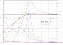
The above is an example of what an aperiodic vent does. The 2 curves are A26RE4 in 35 litres, sealed and with the hole specified in the SEAS A26 document (the big-big peak), the red curve is the target response you are aiming for by putting a highResistance (highR) aperiodic vent into the “hole”.
The highR vents we use in the miniOnkens pushes a reflex box towards an aperiodic box.
The result is a box more tolerant of dynamic changes in T/S so does not move out of tune as much, gives quite elegant refined bass, usually ends up being on the small end of box size, but only goes as low as it goes.
The technique and alignment has worked out very wellin practise, being so versatile as to spawn (likely) 100s of different boxes for many 10s of drivers.

dave
Attachments
This is something which many people want to know more about. Where did you read and learn about these factors?
You should be able to easily find papers and info on all of those. Non of it is obscure knowledge.
- Home
- Loudspeakers
- Multi-Way
- variation in vent tuning frequency