What makes you think an Edcor transformer secondary cannot swing its output voltage beyond the amplifier's supply rails? (0V, +36V)
_
_
Can anybody please give me a hint how this wil sound different to my LM3668 Gainclone monoblocks?
Quite different.
I expect the VFET will be more liquid, filled out with greater levels of small detail reproduced. It will not match as easily with as many speakers.
LeftEar was probably close, these small SE SS amps are bringing small SS amps very close in terms of the subtlety and intamacy that a seamless (no c®ossover distortion) that SETs have been highly regarded for but at a much lower cost (largely in the form of way fewer big transformers).
dave
Using an F4 behind this would definitely have superior damping factor...
Only if superior means bigger, and as we should all know, bigger s not always better.
I hate the term damping. It is a poor way of specifying Rout — hand it to the marketing guys to figure out a way to specify a low number as a big number.
There is a correct Rout for the speaker you are using. We are in a world where currently most speakers are happier with low Rout amplifiers, but with SETs, and now amplifiers like the ACA and now the VFET, the reach and approachability of amplifiers with higher Rout is becoming much larger and users are having to pay attention to the real imedance of their loudspeakers.
dave
Keep in mind that not only does the Edcor swing lots of voltage, but the DC
voltages of the output of the front end and the input to the VFET are different by
approximately the Vgs and are AC coupled through the cap. So no problem there.
At the same time, the front end must swing some voltage beyond the required
output because the Drain impedance affects the gain, causing some loss of swing.
Is it powerful enough to drive ESL-63s to moderate levels? (Used a Sony TA-N5550 ten years ago and liked the honey-dripping sweet sound, but too lean bass so I sold it on.)
An ESL-63 looks like a capacitor — you need to provide considerably more current than in a more resistive loudspeaker. I would suspect it might not be the best match.
dave
What makes you think an Edcor transformer secondary cannot swing its output voltage beyond the amplifier's supply rails? (0V, +36V)
Nothing. I am not looking at the driver stage at all.
Considering the output stage, the article says "...the Vgs value of the VFET ... ranges from 8 volts to 13 volts...". Let's assume you have a 2SJ28 part that needs Vgs = 8 V for correct biasing. Once the 2SJ28 gate is driven with an AC voltage of more than 8 Vpk, the 2SJ28 follower will not be able to follow anymore.
Begin: . . . . gate= +26V . . . . source=+18V . . . . Vgs=8
Peak: . . . . gate= +36V . . . . source=+28V . . . . Vgs=8
Trough: . . . . gate= +16V . . . . source= +8V . . . . Vgs=8
We just made a sinewave of amplitude 10V (20V peak to trough) without clipping. In fact the amplifier output (VFET source) remained 8V away from each rail.
Peak: . . . . gate= +36V . . . . source=+28V . . . . Vgs=8
Trough: . . . . gate= +16V . . . . source= +8V . . . . Vgs=8
We just made a sinewave of amplitude 10V (20V peak to trough) without clipping. In fact the amplifier output (VFET source) remained 8V away from each rail.
We just made a sinewave of amplitude 10V (20V peak to trough) without clipping.
Thanks for realigning my brain. Sorry for the noise.
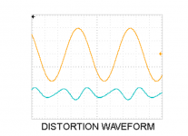
have a question for the s second harmonic distortion waveform,how to use the Oscilloscope get this waveform.
I believe you can apply a heavy notch filter at the fundamental, and then observe the residual
I saw a few waveforms in Mr. Pass's documentation and I would also like to know how to measure it?
I would like to see an idea of balanced +4dBU input front end for this amp. I was using 2x gain transformer (+ LME 49990) in similar context, but I'm sure more interesting design would be possible.
Last edited:
This would be a great opportunity to design one!! The amp and further amplifiers built on this topology and chassis will be around for quite some time.
There are already 6 input stages, your’s can be the 7th!
There are already 6 input stages, your’s can be the 7th!
Ever generous, ever charitable, ever tireless...Thank You Nelson! And to all his supporting cast here at diyA!

I saw a few waveforms in Mr. Pass's documentation and I would also like to know how to measure it?
You don’t have to get a distortion analyzer if you have a good audio interface. With the free REW software and something like a Focusrite Solo, or other brand USB audio interface. More info here:
Howto - Distortion Measurements with REW
... balanced +4dBU input front end for this amp ...
Please by all means, create and contribute one! The more the merrier.
You'll want to figure out the simplest possible way to modify the chassis rear panel, so it can accept balanced input connectors and solidly mount them. Keeping in mind that most DIYers don't have a drill press or access to a machine shop.
Perhaps also decide whether you want to implement a balanced input receiver circuit using ONLY the single ended power supply (+36V, GND) provided within the first approx 90 VFET kits. [Maybe you'll want or insist upon a negative supply voltage too ?]
Mr. Pass,
For a different flavour, could a person purchase some pairs of Sony 2SJ18/2SK60, or, NEC 2SJ20/2SK70, or, Hitachi 2SJ48/2SK133 and be safe for building a future offering from Pass Labs.
If so, would you have a preference for any one of the above transistor pairs?
I am assuming these transistors have a different signature than the Tokin VFET (newbie assumption)?
Thank you.
Last edited:
have a question for the s second harmonic distortion waveform,how to use the Oscilloscope get this waveform.
The second curve is just the remainder that is left after subtracting the fundamental from the amplifier output. All you need is a computer with a decent soundcard and the right software. MATAA will let you do the trick, and I am sure other software packages will do it too.
- Home
- Amplifiers
- Pass Labs
- DIY Sony VFET pt 1