I’m using a 12AT7 grounded cathode gain stage with an HT of 150V. This is giving me around 0.35% THD. Simulation and test results are in rough agreement.
I thought I’d play around with active loading as described in Morgan Jones’ “Valve Amplifiers” to see if I could get a worthwhile reduction in THD.
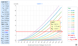
Operating point of the 12AT7 should be in the vicinity of Va 118V, Vg -1V and Ia 1.75mA as shown in the first picture below.
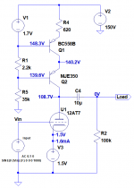
I put together a simulation as shown in the second picture which is based on figure 2.56 of “Valve Amplifiers” 4th edition. I’ve attached the simulation file.
I was expecting to see an order of magnitude reduction in THD. Instead, the simulation is reporting 0.46% which is higher than the standard stage simulation and test.
Why is the simulation not reporting a significant improvement in THD?
I thought I’d play around with active loading as described in Morgan Jones’ “Valve Amplifiers” to see if I could get a worthwhile reduction in THD.
Operating point of the 12AT7 should be in the vicinity of Va 118V, Vg -1V and Ia 1.75mA as shown in the first picture below.
I put together a simulation as shown in the second picture which is based on figure 2.56 of “Valve Amplifiers” 4th edition. I’ve attached the simulation file.
I was expecting to see an order of magnitude reduction in THD. Instead, the simulation is reporting 0.46% which is higher than the standard stage simulation and test.
Why is the simulation not reporting a significant improvement in THD?
Attachments
Using Adrian Immlers ECC81 model I get 2.78Vrms @ 0.13% distortion for CCS, 1.94Vrms @ 0.38% distortion for a 39k load. Both with ~90V anode and 1.55mA. The improvement you get with a CCS is limited by the 100k load which is effectively in parallel with the anode load.
Thanks tikiroo. I've just downloaded Immler-Tubes_20210118.zip.
It contains ECC81,RFi4.txt and ECC81_i2.txt. Did you use one of these?
What do I need to do to use them?
It contains ECC81,RFi4.txt and ECC81_i2.txt. Did you use one of these?
What do I need to do to use them?
I thought I was using the RFi4 model but had models mixed up in my files and the figures I gave were for another more simple model. Redone with Adrian's model has worse distortion but still moving the right way:
CCS - 3.14Vrms @ 0.44% 116V anode
22k - 1.81Vrms @ 1.18% 116V anode
To use the model, rename as .lib instead of .txt and call it with a spice directive. Or just paste the entire text into a spice directive.
CCS - 3.14Vrms @ 0.44% 116V anode
22k - 1.81Vrms @ 1.18% 116V anode
To use the model, rename as .lib instead of .txt and call it with a spice directive. Or just paste the entire text into a spice directive.
ECC81 is not the most linear tube used in this way, and obviously there are big differences in the various models out there. I tried the ayumi model and got different results again, although not too far away from Adrians.
Thanks. The 12AT7 is a fixture in the four-way crossover I'm working on.
If the active load made a huge difference I could pretty easily add a little PCB to replace the 39k resistor in the gain stage.
I'll breadboard it anyway even if just to see if the simulation matches reality.
If the active load made a huge difference I could pretty easily add a little PCB to replace the 39k resistor in the gain stage.
I'll breadboard it anyway even if just to see if the simulation matches reality.
Looking at the 12AT7/ECC81 curves, I would use an IXYS 450 or 900 current source for the plate load,
and I would start with these quiescent operating conditions:
IXYS set for 6mA
300V B+
200V plate
100V across the IXYS part
-2V grid bias (I would use self bias, 330 Ohm Rk, and a bypass capacitor). That gives 198V plate to cathode, and -2V bias, close enough.
Then, I can input a signal of +1V to -1V peaks. That takes the grid from -1V to -3V on the curves.
The nice thing about that is the grid never gets closer than -1V.
If the grid was allowed to get closer than -1V, the grid impedance can change, due to the contact potential or other effects.
What is wrong with using a little more plate voltage, and a little more plate current?
Just because it is a preamp, or a line amp, does not mean you can not start with 300V B+.
(Or do you think so?)
Try that in your simulator.
THD?
2nd HD?
3rd HD?
Of course, that may or may not work better.
I have to give credit to one of the posters on this forum (my old brain is drawing blanks for names today), he used a quote from the 1800s as his tag line:
“In theory, there is no difference between theory and practice.
But, in practice, there is.”
THD goes with signal level. Pick an output signal level and adjust your experiment to have nearly the same output signal in each case. Otherwise you just get dizzy.
Are you trying to find lower THD? 22k is a heavy load on 12AT7 especially at 1.6mA. You want the DC feed resistor somewhat higher than the triode internal resistance. 12AT7 is ~~20k but at much higher current.
Even the 100k external load is a hit on 12AT7 at few-mA.
THD goes with signal level as a function of supply voltage. 150V is good for 20Vrms at 5% THD, and less at lower level, so 0.5% at 2Vrms. If you can't approach that performance you are misbiased or heavy-loaded.
Looking at the 12AT7/ECC81 curves, I would use an IXYS 450 or 900 current source for the plate load,
and I would start with these quiescent operating conditions:
IXYS set for 6mA
300V B+
200V plate
100V across the IXYS part
-2V grid bias (I would use self bias, 330 Ohm Rk, and a bypass capacitor).
I did the simulations using the conditions the OP gave, but yes, I have used the ecc81 at similar conditions as you state, gives significantly lower distortion. Eli Duttman has said that 200V plate and 3mA current sounds good, and used that in his "El Cheapo" design.
A 12AT7 in an "EL Cheapo", has the cathodes tied together, and a current sink for the cathodes.
That is a Differential Stage (differential phase splitter, in this case).
The distortion of a single 12AT7 triode is 2nd harmonic.
But with the cathodes tied together, and a current sink from those cathodes to ground, that Intrinsically (automatically) reduces the 2nd harmonic distortion of each triode, as their cathodes are trading off which tube has the most signal current.
That means the Total Harmonic Distortion is very well cancelled, because of the Differential circuit.
At some large signal level, the 3rd harmonic rises rapidly, which brings the THD up again.
Now you know why I use a dual triode 12AY7, with cathodes connected together, and an LM334 current sink from the cathodes to ground.
That is my favorite way to drive a push pull output stage.
Context
Thanks for the responses. The gain stage precedes a buffer and some filters in a 4-way crossover.
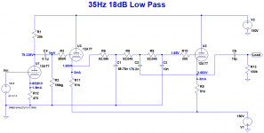
The 35Hz low pass section is shown below. 12AT7s are used throughout. There's a Transformer Volume Control (TVC) on the front end and a single-ended to balanced transformer on the output.
I was asked to add a gain stage and buffer in front of the cathode follower filters when the output level was found to be insufficient.
The ±150V rails are a given.
The comments about the 12AX7/ECC83 have got me thinking though that there’s no reason I have to use 12AT7s for the gain stage and buffer. The 12AX7 provides more gain and is more linear.
Thanks for the responses. The gain stage precedes a buffer and some filters in a 4-way crossover.
The 35Hz low pass section is shown below. 12AT7s are used throughout. There's a Transformer Volume Control (TVC) on the front end and a single-ended to balanced transformer on the output.
I was asked to add a gain stage and buffer in front of the cathode follower filters when the output level was found to be insufficient.
The ±150V rails are a given.
The comments about the 12AX7/ECC83 have got me thinking though that there’s no reason I have to use 12AT7s for the gain stage and buffer. The 12AX7 provides more gain and is more linear.
Attachments
Why is my gain stage with cascode CCS active load very noisy?
I only have 150V available for a gain stages preceding a bunch of 12AT7 cathode follower crossover filters so I’m investigating an active load as suggested in chapter 2 of Morgan Jones’ “Valve Amplifiers”.
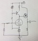
The schematic is shown below. It’s based on Morgan Jones 3rd Edition Fig 2.51. The 7N7 is replaced by a 12AX7A with other changes as required to accommodate the different tube and lower HT. The original circuit’s cathode zener has been replaced by a diode. The lower HT means I can take advantage of the slightly higher hfe of an MPSA92 instead of the MJE350 in the book.
The simulation suggests a gain of 39dB which is an 11dB improvement over the original 12AT7 stage.
I’ve added the measured voltages in red. The anode voltage is 30V higher than the simulation but all other voltages are pretty close. I can reduce the anode voltage by increasing R4 and the constant anode current.
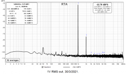
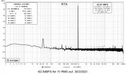
The second image shows the 1kHz spectrum of the original 12AT7 stage. THD is 0.26% which is pretty close to the simulation. Noise floor for this measurement is about -107dB.
The third image shows the 1kHz spectrum for the 12AX7A stage with the active load. Input level is reduced by 12dB to match the output levels and the THD is lower but the noise is significantly higher (11dB).
Why is my gain stage with the cascode CCS active load so noisy? No zeners to bypass.
I only have 150V available for a gain stages preceding a bunch of 12AT7 cathode follower crossover filters so I’m investigating an active load as suggested in chapter 2 of Morgan Jones’ “Valve Amplifiers”.
The schematic is shown below. It’s based on Morgan Jones 3rd Edition Fig 2.51. The 7N7 is replaced by a 12AX7A with other changes as required to accommodate the different tube and lower HT. The original circuit’s cathode zener has been replaced by a diode. The lower HT means I can take advantage of the slightly higher hfe of an MPSA92 instead of the MJE350 in the book.
The simulation suggests a gain of 39dB which is an 11dB improvement over the original 12AT7 stage.
I’ve added the measured voltages in red. The anode voltage is 30V higher than the simulation but all other voltages are pretty close. I can reduce the anode voltage by increasing R4 and the constant anode current.
The second image shows the 1kHz spectrum of the original 12AT7 stage. THD is 0.26% which is pretty close to the simulation. Noise floor for this measurement is about -107dB.
The third image shows the 1kHz spectrum for the 12AX7A stage with the active load. Input level is reduced by 12dB to match the output levels and the THD is lower but the noise is significantly higher (11dB).
Why is my gain stage with the cascode CCS active load so noisy? No zeners to bypass.
Attachments

Good point. Where is the noise coming from?
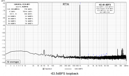
If I run my soundcard interface in loopback with the same input signal level (-63.5dBFS or ~120mV RMS) I get the distortion profile shown below. Noise floor is less than -130dB.
My ±150V rails and 12.6V heater supply are regulated.
Interesting that it shows 0.2% THD.
If I run my soundcard interface in loopback with the same input signal level (-63.5dBFS or ~120mV RMS) I get the distortion profile shown below. Noise floor is less than -130dB.
My ±150V rails and 12.6V heater supply are regulated.
Interesting that it shows 0.2% THD.
Attachments
DN2540 enhancement MOSFET make a better current source.
post #12 , R4 = 220k C4 = 0.22 uf. AS drawn it will take that circuit *minutes* to reach 0 grid volts on the follower 12AX7 tube
post #12 , R4 = 220k C4 = 0.22 uf. AS drawn it will take that circuit *minutes* to reach 0 grid volts on the follower 12AX7 tube
Last edited:
Is the U1 grid leak resistor omitted?
Yes. In the tube crossover units a Transformer Volume Control drives the grid of the gain stage so no need for one. In my test set-up I didn't bother to include one because it's being driven by a low impedance source.
DN2540 enhancement MOSFET make a better current source.
post #12 , R4 = 220k C4 = 0.22 uf. AS drawn it will take that circuit *minutes* to reach 0 grid volts on the follower 12AX7 tube
Thanks. The 10uF was a typo left over from when I deleted all the crossover filter stages from the schematic leaving only the 10uF output capacitor.
Maybe not a coincidence that you have 11-12 dB increase in gain and an 11 dB increase in noise?
After thinking more about your response I realise that maybe there's not actually a problem here at all which is probably what you meant. Just took a while to sink in.
Noise floor of my test set-up is a bit less than -130dB.
The 12AX7A gain stage provides a gain of 39dB which raises the noise floor to -130dB plus 39dB or ~90dB which is what I'm measuring.
From the tests I've done, using the same amount of sand, it's better to have a simpler CCS but buffer the output (mainly with 12AX7, but with 12AT7 too).
Like this (please check it with simulations, I've sketched it by memory and it could be wrong EG it could be needed a resistor in series between mosfet gate and CCS to drop the voltage)

Like this (please check it with simulations, I've sketched it by memory and it could be wrong EG it could be needed a resistor in series between mosfet gate and CCS to drop the voltage)
Attachments
Last edited:
- Home
- Amplifiers
- Tubes / Valves
- Grounded cathode stage THD reduction with active load