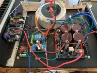
Two boards done! Had an hard time cleaning the flux mess [emoji1].
Now i need to buy the heatsinks to start testing this guys[emoji6].
I used this 0.1ohm 5w green resistors, are this ok? The white ones i bought from mouser were too big and they do not fit.

Now i need to buy the heatsinks to start testing this guys[emoji6].
I used this 0.1ohm 5w green resistors, are this ok? The white ones i bought from mouser were too big and they do not fit.
The story continues......Today I tried to set the VAS, but the mV value didn't want to change, still 0mV, even though I was rotating VR1 and VR2. As the VR2 rotates, LED D6 dims to completely dark. If I turned the trimmer back to the maximum resistance, then is the light back on D6 😕
Something is better... 🙂 LED D6 does not need to be changed. It was in poor contact between the Q8 and the PCB.
Something is still the same... 🙁 The VAS biasing cannot be set. Multimeter still shows 0.0mV, even if I turn VR1, VR2 for a long time and no change in values. I checked all the trimmers and they are functionally good.
The LEDs are bright, I checked all the transistors for continuity between the collector and the emitter. Before that I checked them for a diode test between the base and the colector-emitter. I replaced some transistors, but there was no need, they were good.
Nothing heats up, nothing burns, ...the board looks fine. I don't know what to do next...

shaan heeelp 😕 Thank you
Hi Robodo.
Check all the glass diodes as well as the following test, all with power removed and all onboard capacitors drained.
Check all the BJTs for collector to emitter conduction with meter's diode test mode. For npn red probe to collector and for pnp black probe to collector. Note down the readings for each transistor.
Short base and emitter of each transistor and test collector to emitter conduction again. Note down the readings for each transistor and share the results here so that I can have a look.
Bests,
shaan
Hi shaan,
Thank you for instructions. I'm at work now, as soon as I get home, I'll try to do what you tell me to do. And then I'll write you what I measured.
Thank you.
Thank you for instructions. I'm at work now, as soon as I get home, I'll try to do what you tell me to do. And then I'll write you what I measured.
Thank you.
So the glass diodes are good, the capacitors are discharged.
Measurements written, the results are here:
1. Measurements
NPN Tranzisrors:
Q2 --
Q4 --
Q6 0,362 V
Q8 0,245 V
Q10 --
PNP Tranzistors:
Q1 --
Q3 --
Q5 0,362 V
Q7 0,475 V
Q9 --
2. Measurements (base with emitter shorted)
NPN
Q2 --
Q4 --
Q6 0,362 V
Q8 1,00 - 0,873 V (gradually decreased)
Q10 --
PNP
Q1 --
Q3 --
Q5 0,363 V
Q7 0,434 V
Q9 --
So the glass diodes are good, the capacitors are discharged.
Measurements written, the results are here:
1. Measurements
NPN Tranzisrors:
Q2 --
Q4 --
Q6 0,362 V
Q8 0,245 V
Q10 --
PNP Tranzistors:
Q1 --
Q3 --
Q5 0,362 V
Q7 0,475 V
Q9 --
2. Measurements (base with emitter shorted)
NPN
Q2 --
Q4 --
Q6 0,362 V
Q8 1,00 - 0,873 V (gradually decreased)
Q10 --
PNP
Q1 --
Q3 --
Q5 0,363 V
Q7 0,434 V
Q9 --
The only thing that stands apart from the rest (considering all the other BJTs are okay) is Q8. If you haven't already, desolder that transistor and check it separately. Before removing check whether Q8 passes the base-emitter and base-collector test, the reading should be 700-800mV in both cases, check for the same after removal.
Work in progress. Not sure of final layout, Just ENJOYING the Music!
Still waiting on parts.
 🙂
🙂Hi shaan,The only thing that stands apart from the rest (considering all the other BJTs are okay) is Q8. If you haven't already, desolder that transistor and check it separately. Before removing check whether Q8 passes the base-emitter and base-collector test, the reading should be 700-800mV in both cases, check for the same after removal.
it is interesting that I have replaced this transistor before.
But I won't change it until Monday. Now I have to dedicate time to my family and other activities.

Thank you so much shaan for your help.
Hi shaan,The only thing that stands apart from the rest (considering all the other BJTs are okay) is Q8. If you haven't already, desolder that transistor and check it separately. Before removing check whether Q8 passes the base-emitter and base-collector test, the reading should be 700-800mV in both cases, check for the same after removal.
so transistor Q8 was good, but to be sure I soldered a new transistor. Maybe a bad connection on the PCB. But nothing has changed, again the same story. 😕
So I once again measured the components on the board and the connections between them.
... and finally, I found the wrong connection between bases Q1 and Q2. 🙂 I changed Q2 before, but I only found out the wrong contact now. Exactly the pin from the base of Q2 was soldered on the bottom layer, but it was not connected to the top layer, so there was no connection to Q1 and the input.
And then I put the board on the heatsink, connected the power supply and ... the VAS value goes up
 Then I set Offset and Mosfet biasing
 ... I'm happy, I can drink it now

Thank you very much shaan for your advice and your time.

I hope there will be no problem.
Hi Robodo.
Very happy to know you figured out the problem! Looking forward to hear your impression when the modules are playing music.
🙂
Very happy to know you figured out the problem! Looking forward to hear your impression when the modules are playing music.
🙂So I managed to connect all the modules. Just so I can briefly connect it to my main speakers. So far without the front panel, it did not affect the quality of music reproduction 😀
I had a short time to listen ... but he plays beautifully.
I found out that there are a lot of members who owned the FO 1.4 M amplifier, I am one of them. FO was not bad, but frequent failures and no support redirected me to V4H and so far I am satisfied. 🙂
I had a short time to listen ... but he plays beautifully.
I found out that there are a lot of members who owned the FO 1.4 M amplifier, I am one of them. FO was not bad, but frequent failures and no support redirected me to V4H and so far I am satisfied. 🙂
Attachments
So I managed to connect all the modules. Just so I can briefly connect it to my main speakers. So far without the front panel, it did not affect the quality of music reproduction 😀
I had a short time to listen ... but he plays beautifully.
I found out that there are a lot of members who owned the FO 1.4 M amplifier, I am one of them. FO was not bad, but frequent failures and no support redirected me to V4H and so far I am satisfied. 🙂
one more ex FO 1.4M 😀
- Home
- Group Buys
- PeeCeeBee V4H GB