
Correct, about that ballpark, you could replace the entire CCS with a 10M45S with like 10K 2W in series to eat some of the Dissipation.
2x 220K means those Leds are starved of the current they need to operate in the linear part of the U/I characteristics.
2x 220K means those Leds are starved of the current they need to operate in the linear part of the U/I characteristics.
For the 2N3904, the base voltage is the typical red LED voltage, about 2V.
The Vbe is about 0.65V, so the emitter voltage Ve = (2V - 0.65V) = 1.35V.
Then Ic ~ Ie = (1.35V / 180R) = 7.5mA which is about equal to Ic for the MJE340 as well.
The Vbe is about 0.65V, so the emitter voltage Ve = (2V - 0.65V) = 1.35V.
Then Ic ~ Ie = (1.35V / 180R) = 7.5mA which is about equal to Ic for the MJE340 as well.
Last edited:
Thanks. I figured 1.7V across each LED and then 0.7V from base and emitter of the transistor leaving 1V across the resistor to set the current. That's from memory so I could be mistaken. But maybe the calculation would be different with the low current through the LEDs. I'm getting significant distortion through the amp, but I'll need to do further measurements to check the current and voltages. I've just tested out my VTVM which I think will be needed to check the bias voltages on the 6CG7.
Rayma, your calculations are encouraging, because 5.5mA seems on the low side of optimal for a 6CG7 LTP/driver.
Last edited:
Yes, you can adjust the 180R accordingly. The actual red LED voltage will vary somewhat with the particular device. Measure that under actual operating current for the LEDs (which seems a bit low right now), and recalculate
the value of the 2N3904 emitter resistor for the combined plate current that you want.
I would tend to use more like 5mA in the LEDs, if it is available from the supply. Right now it's about 1mA.
That's kind of marginal considering that it also feeds the base currents for the two transistors.
the value of the 2N3904 emitter resistor for the combined plate current that you want.
I would tend to use more like 5mA in the LEDs, if it is available from the supply. Right now it's about 1mA.
That's kind of marginal considering that it also feeds the base currents for the two transistors.
Last edited:
Yeah I might just adjust to a value that gives decent current and bias voltage. It would be good to know the original design spec, but I can't expect support since Classic Valve doesn't offer this board any more. I could spice it, but I have no idea where to find the device models.
I've used that board at least twice by subbing in a DN2540, a pot, and a 1k snubber. Forget the two 220k, the two LED and the two transistors. You can get it to all fit using existing holes without cutting any traces. I mount the DN2540's underneath with small heatsinks.
I've also run the 6EJ7 in triode. Again you can do it without cutting traces.
I've also run the 6EJ7 in triode. Again you can do it without cutting traces.
I get 9.98mA for MJE340 collector current when I run the model in LTSpice
Thanks much! I measured my 10m45s circuit at about 6.8mA, so I'll change it to about 10mA and see if that cleans up the distortion. Thet current across the 47k plate resistors agrees.
I got crazy values trying to read the grid voltages on the 6CG7 with a VTVM, one higher and one lower than the cathode. I do have spice models for the tubes, I'll have to spice the circuit to determine what the bias is supposed to be.
I've also run the 6EJ7 in triode. Again you can do it without cutting traces.
I may try that eventually, especially if I end up running the output tubes in triode (for now ultralinear.)
If you read the grid voltages with a 10 meg-ohm input resistance voltmeter, you will get different voltages because one of the 6FQ7 grids is sourced through the plate resistor of the 6EJ7, while the other grid gets its bias through that resistance plus an additional 1Meg, and your meter will load that down more.
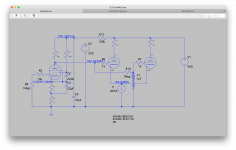
I played around in spice to find where the DC voltages land. It looks like with the stock schematic 5.5mA is plausible for the CCS, giving about -3.5v bias on the 6CG7. That seems on the edge, if the EL34s are biased at -34v, and the gain of a 6CG7 section is about 10 in this circuit. Increasing the CCS current will reduce Vgk.
Other ways to tweak to increase Vgk are reducing the phase splitter plate resistors, or reducing the B+ voltage for the input stage.
Other ways to tweak to increase Vgk are reducing the phase splitter plate resistors, or reducing the B+ voltage for the input stage.
Attachments
- Home
- Amplifiers
- Tubes / Valves
- LTP CCS current