I have two HK PM660s, both of which have dead preamps and working main amp sections. One I will fix and bring back to 100%, the other I would like to make into a basic power amp if possible.
Using this situation as a learning exercise, so please know I'm not hacking away willy-nilly.
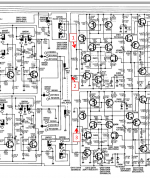
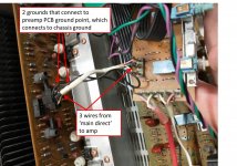
From the 'main direct' switch I see two sets of wires going to and returning from the preamp PCB (red and white bundles), and one set that goes directly across to the main amp PCB via a plug w/ 5 wires going in, a white wrap with three wires from the 'main direct' switch area, joined by two ground wires that connect to a ground point on the preamp PCB which connects to a chassis ground.
So, could I essentially bypass everything and connect the input L&R to the main amp (points 1&3 on the attached pic)? For the ground I'm not so sure. To mimic the original circuit I would tie the input grounds together and run them to the main amp PCB (replace the central black wire in the bundle). I would then keep the two grounds running from the main PCB and connect them to the chassis ground. I know I'm not explaining that very well.
I am sure I am missing some key points, and will wait until I hear back before I do anything!
Thanks
Using this situation as a learning exercise, so please know I'm not hacking away willy-nilly.
From the 'main direct' switch I see two sets of wires going to and returning from the preamp PCB (red and white bundles), and one set that goes directly across to the main amp PCB via a plug w/ 5 wires going in, a white wrap with three wires from the 'main direct' switch area, joined by two ground wires that connect to a ground point on the preamp PCB which connects to a chassis ground.
So, could I essentially bypass everything and connect the input L&R to the main amp (points 1&3 on the attached pic)? For the ground I'm not so sure. To mimic the original circuit I would tie the input grounds together and run them to the main amp PCB (replace the central black wire in the bundle). I would then keep the two grounds running from the main PCB and connect them to the chassis ground. I know I'm not explaining that very well.
I am sure I am missing some key points, and will wait until I hear back before I do anything!
Thanks
Attachments
Last edited:
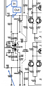
The power amplifier input is at a high impedance and is a mos gate. Maybe change the 120k to 10k.
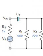
Perhaps add a 10uF bipolar electrolytic input blocking capacitor there also.
Perhaps add a 10uF bipolar electrolytic input blocking capacitor there also.
Last edited:
Thanks rayma, appreciate it. Would that be the 439, 440, 401 and 402? And the cap in line with the input like the attached pic?
I think I get the gist of what you are suggesting, if you can point me to any resources or search terms the describe it that would be great.
Would those changes effect the sound of the amp?
I think I get the gist of what you are suggesting, if you can point me to any resources or search terms the describe it that would be great.
Would those changes effect the sound of the amp?
Attachments
The power amplifier input is at a high impedance and is a mos gate. Maybe change the 120k to 10k.
Perhaps add a 10uF bipolar electrolytic input blocking capacitor there also.
10 kOhm is a bit too low for some sources. Will there be a volume potentiometer? Then leave the 120 kOhm but use 1 or 2.2 µF film caps as DC blocker indeed. When possible replace 100 kOhm volume control to 20 or 25kOhm.
When using the device as a power amp 25 kOhm for the resistors R401/402 would be a good choice as every source can have that load normally. Still use 4.7 µF coupling caps (always film).
* Definitely leave the input RC filters where they are! So R501/502 and C501/502.
Last edited:
Making sense. This will be used with common solid state preamps, I just finished a Korg B1, have an Adcom and another DIY in the works. All will have volume controls so this can be a straight power amp.
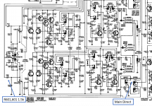
I mislabeled my first image, but R501/502 and C501/502 are just before the volume control, correct?
Edit- updated the image to add the coupling cap before it goes into the main amp.
I mislabeled my first image, but R501/502 and C501/502 are just before the volume control, correct?
Edit- updated the image to add the coupling cap before it goes into the main amp.
Attachments
Last edited:
When using the device as a power amp 25 kOhm for the resistors R401/402 would be a good choice as every source can have that load normally. Still use 4.7 µF coupling caps (always film).
Is the value for R401/402 the input impedance? The methodologies for calculating it seem very complicated. I was playing around with a coupling cap calculator: Coupling Capacitor Calculator by V-Cap
Also thank you for the response jean-paul.
The best IMHO:
RC Low-pass Filter Design Tool
Please note to write values according the convention so "4.7u" and "25k" in this particular online tool.
yes, simple looking things can be complicated. This is the case with inductive and capacitive things 😀 Also note that those two 4.7 µf caps (preferably choose 5 mm pitch 4.7 µf 50V types) are the only way to prevent the amplifiers to amplify DC! Suppose a source/buffer/preamp that suddenly has a DC voltage at its outputs of let's say +2V..... the sweet smell of burned woofers in the morning.
Last edited:
Thank you! Yes those caps are going in, I just wanted to do some maths to learn a little more about figuring out the input impedance and then cap size.
Which is tough, formulas genuinely make my head hurt these days!
Which is tough, formulas genuinely make my head hurt these days!
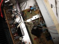
She lives!! Forgive the hack job this is just for testing. The pictures are just for proof I did something, very hard to see so in sum:
1) Kept RF blocker (right term?) intact by running L&R inputs run into R501, then C501 to ground, then into 4.7uF film cap and into amp.
2) Originally ran signal grounds and C501 ground point into amp, okay but bad hiss. Separated signal input grounds to run into amp, C501 grounds tie to ground point collector on tone board. Hiss seems better.
3) removed the input selector and volume board, all connectors I could.
There does seem to be a decent amount of hiss, any culprits for that? Could absolutely be my very shoddy wiring so that may clean up. Next is figuring out how to mount the new input section, the 4.7uf cap is sturdy enough I'm tempted to clear off a spot on the preamp board and glue it down.
I used this cap and resistor, the 4.7 is the coupling cap and the resistor is to replace the R401/402 which were 120k with 25k.
Blocked
Blocked
Thanks all!
Attachments

Where have you found the ground?
Wiring looks strange. Can you draw exactly how is it connected?
Wiring looks strange. Can you draw exactly how is it connected?
Last edited:
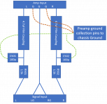
Thanks- maybe this will help. Here's the scheme I tried to follow after attempting to trace the PCBs.
I used two grounds -
1) I ran the signal grounds together into the amp
2) Tied C501&502 together to the pin on the preamp PCB that for lack of a better word looks like a ground collection point. Ground wires from multiple PCBs collect then go to a single chassis ground.
On the drawing the dark red grounds coming out of the amp are original, the green are the ones I added.
Attachments
Last edited:
Whether this means anything I shorted the inputs and the hiss went away.
I traced the PCBs again and all the ground points basically tie into the middle wire of the 3-wire hookup scheme that runs throughout the amp. The only other thing is the inputs also tie to the chassis in the back through a small capacitor.
So C501&502 actually share the same ground trace as the input signal ground which is what I originally had. I've tried multiple combinations of grounding without much difference.
Bit stumped at this point. For the final wiring I was going to put the RCAs in the back and use a similar point to point layout using the big 4.7's as an anchor. Cleaning that up might help.
From gootee - Signal Ground
The signal input 'ground' should not really be thought of as a ground. It is only the reference voltage for the input signal.
Typically, the signal input 'ground' is NOT connected to the chassis at the point of entry (use insulated RCA jacks), and is only connected directly to the signal ground reference point in the input stage. From there, there should be a separate signal ground-return path, all the way to the main 'star ground' point (where all of the separate ground returns meet at only one point).
The input signal ground reference point might also include a feedback divider ground and a lowpass RF filter ground, and a highpass DC-blocking filter ground. The signal input reference ground's star-ground-return path could also include an optional 'ground separator' resistor of a few ohms, which should not be needed if the whole grounding scheme is ideal.
Last edited:
Not that anyone was holding their breath but this has been a fun project and it's really working well. I cleaned up the wiring and the noise is gone.
Still fighting a high DC offset at startup, though it eventually settles down.
Always so grateful for the willingness to help, even when it probably seems like a silly project.
Still fighting a high DC offset at startup, though it eventually settles down.
Always so grateful for the willingness to help, even when it probably seems like a silly project.
- Home
- Amplifiers
- Solid State
- Bypass dead preamp - Kardon PM660