Having trouble figuring out the PS which is using an SG3524 in this amp, which came in with one FET shorted.
First I took out just that one shorted FET, and it seemed to me that none of the others were shorted, so I went to power and it draws excessive current. I pulled the rectifiers and same - excessive draw. Then I took out all the FETs which are IRF3205 (47 ohm gate resistors are good), and I removed Q109 (2n2222A) and Q110 (A1562) which were controlling the side of the FETs which had the one failure (Q106) from the board to test and all the drivers seem to be OK as of now.
So, now the amp takes power but I think there is something going on with the SG3524, but I'm a little rusty. I know that pins 4/5&8 should be close to 0, especially since pin 8 is ground, but instead all three have ~7vDC.
SG3524 (U101) via Fluke 16
1: 4.12
2: 5.32
3: 9.72
4: 6.98
5: 6.98
6: 8.75
7: 7.88
8: 6.98
9: 6.94
10: 6.84
11: 6.04
12: 13.35
13: 13.35
14: 6.06
15: 12.64
16: 10.65
At this point I'm expecting either the SG3524 has failed or something registering on one of the other pins is forcing pins 4&5 to go high. I do notice someone previously changed out all FETs, and all drivers, but SG looks original. It suspect?
I don't have my oscope just yet unfortunately. Darn USPS is taking forever and blaming weather.
Last edited:
Thanks. There are no burned traces on this board, and now that I look closer looks like both ICs were probably replaced previously. I'm thinking the previous repair did not re-install a jumper from ground to 4/5/8. I went ahead and did so and now the SG is measuring a little better, though I'm not sure why pin 11 and pin 14 are outputting differently at this point. Pin 11 is running to the side which had the single failed FET btw:
SG
1. 2.549
2. 2.549
3. 0.292
4. 0.000
5. 0.000
6. 3.502
7. 2.189
8. 0.000
9. 0.790
10. 0.009
11. 0.121 <--
12. 13.35
13. 13.35
14. 0.717 <--
15. 12/65
16. 5.12
I re-installed a pair of 'good' FETs one onto each side of the board. The gates are measuring 0.470 and about 1.0v. Something isn't even. Either a driver or the SG is still amiss. Probably a driver I guess. Very difficult to tell until I get my equipment. I'm getting different readings comparing the driver sets across the board:
Pin 14 (0.717v) traces to the Q107&Q108s, which output about 1v to the gates.
Pin 11 (0.121v) traces to the Q109&Q110s, which output about 0.47v to the gates.
I did bench test Q109 and Q110 out of circuit and they seemed to check when walking the legs.
Nothing is getting hot. No significant amperage draw. No rectifiers.
Yes (1k resistors are good) and Yes same voltage on 12 & 13.
Are IRF3205 with 47ohm gate resistors appropriate for this amp or is there a better option? Originals were 3.3 ohm and RFP50N05 I believe.
Thank you
Are IRF3205 with 47ohm gate resistors appropriate for this amp or is there a better option? Originals were 3.3 ohm and RFP50N05 I believe.
Thank you
Where I ran a jumper to ground pins of the SG3524, I also had to do the same to pin #7 of the MC14106B as that IC didn't have ground run either.
Amp powers and draws excessive current but my PS is current limiting so I can troubleshoot.
Opamps are getting proper voltage as in regulated side looks good, +-16vDC or so. Rail voltage is OK.
Right channel is putting rail voltage out the speaker terminals. None of the TIP outputs are shorted. The MSPA14 under the board of that channel I'll call 'suspect' at this point but is seems to be measuring OK.
I noticed someone messed around with the driver board of that channel but it was testing -ok- on the board. I removed BOTH driver boards.
Thats when I found two issues. On the problem channel, the 49.9ohm resistor (R221) going to the 2SA1479 was blown open. The 1479 is testing identically from board to board so it *may* be OK.
and THEN I noticed a possible manufacturing flaw. Take a look at the attached photo. On the Top RIGHT board you'll first see I installed a 47 ohm in place of the failed 49.9ohm as that is what I have on hand. Then, just next to that 1.33k and 976 ohm resistors. Now - take a look at the BOTTOM driver board - same resistors.
The board on the top seems to have these installed backward. I'm going to swap the resistors back.
Could this mistake have caused this amp to fail - ie R221 to blow open, and then blow all the way back to the PS? What about all these driver transistors - suspect?
Attachments

Last edited:
I don't think that that factory defect could have caused the amp to fail.
The 49.9 ohm resistor generally only fails when an output or driver fails.
The 49.9 ohm resistor generally only fails when an output or driver fails.
Thanks I'll comb through those when I get this amp to turn on with stability.
In my adventure, I'm 100% sure I fried the MC14106B Hex Trigger which may have also taken out the SG3524. I accidentally shorted pins 13 & 14 and then lost all signal from pins 11&14 of the SG. The MC14106B also started outputting full 13vDC across all output pins. Dang.
Is there something I can use in place of U102? MC14106B seems only to be available from eBay/china/expensive. There are quite a few SMD versions which I could use a converter I guess, or perhaps there is another IC that will work, like the CD40106BE?
https://datasheet.octopart.com/MC14106BDG-ON-Semiconductor-datasheet-9718987.pdf
Thank you
CD40106BE is not the same at all. 14 vs 16 pin to start.
I'm back in this amp though as I was able to snag a MC14106B from another amp. I am able to get power, and even rail voltage. Seems everything on the output side may be OK,
Except the amp draws excessive current at idle. Up to about 3A. The PS FETs get warm.
I pulled out the rectifiers which are testing out fine and PS still draws excessively. Something is going wrong in the PS section for sure. New IRF3205 with 47ohm gate resistors.
I pulled out the PS drivers and they all tested fine. I put new 2n2222a drivers in and that didn't help. Re-used original A1562 drivers.
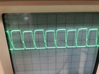
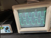
With my scope, pins 11 & 14 from the SG look good all the time. On the gate resistors however theres a bit of a notch going on.
Are 47 ohm resistors not low enough to drive the IRF3205?
Photo coming
I'm back in this amp though as I was able to snag a MC14106B from another amp. I am able to get power, and even rail voltage. Seems everything on the output side may be OK,
Except the amp draws excessive current at idle. Up to about 3A. The PS FETs get warm.
I pulled out the rectifiers which are testing out fine and PS still draws excessively. Something is going wrong in the PS section for sure. New IRF3205 with 47ohm gate resistors.
I pulled out the PS drivers and they all tested fine. I put new 2n2222a drivers in and that didn't help. Re-used original A1562 drivers.
With my scope, pins 11 & 14 from the SG look good all the time. On the gate resistors however theres a bit of a notch going on.
Are 47 ohm resistors not low enough to drive the IRF3205?
Photo coming

CD40106BE is not the same at all. 14 vs 16 pin to start.
I deleted that post after I seen the search box returned the incorrect part. Why it's still here, I really don't know.
R105 and R106.
Before I read your post, I changed out the 47ohm gate resistors to 10ohm and the amp powers with only .7A draw. Fets stay cool-er.
Should I still try changing the pull down resistors?
Before I read your post, I changed out the 47ohm gate resistors to 10ohm and the amp powers with only .7A draw. Fets stay cool-er.
Should I still try changing the pull down resistors?
There are multiple solutions. If yours works, that's likely good enough. It's a bit harder on the drivers but the drivers you used should have no problem with the load.
Thank you. I'm still combing through this amp. Had one set of bad TIP107s which were putting DC on the speaker terminals under power, driver boards, etc. Working on it...
BTW What should I set bias to on this amp being a class A? About 0.050vDC?
BTW What should I set bias to on this amp being a class A? About 0.050vDC?
All tip10x replaced, and also replaced the bias transistors and both driver boards. Took all that to keep this amp from running away with outputs getting hot on the bench. Now it’s idling at 1.4A with bias totally off. Barely gets warm now. Seems stable enough to continue. This amp sure took a lot of parts lol.
- Home
- General Interest
- Car Audio
- Soundstream Reference Class A 6.0