Hi folks
I just bought a power amp and there is brown gunk surrounding the base of all four smoothing caps (two per channel) so I think it's wise to replace them, especially as they are Jamicons and are probably of dubious quality anyways.
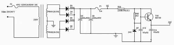
Here's the circuit they are in, they are 2200uF 63V units.

I have some ELNA 10000uF 63v caps I would use, but they are too big to physically fit.
The only other large value caps I have that would physically fit are some 6800uF Dubiliers but they are only rated for 35V.
What voltage rating would replacement caps have to be - 63V or would 50V suffice?
Is there an advantage to using larger values than the 2200uF it has installed?
I just bought a power amp and there is brown gunk surrounding the base of all four smoothing caps (two per channel) so I think it's wise to replace them, especially as they are Jamicons and are probably of dubious quality anyways.
Here's the circuit they are in, they are 2200uF 63V units.
I have some ELNA 10000uF 63v caps I would use, but they are too big to physically fit.
The only other large value caps I have that would physically fit are some 6800uF Dubiliers but they are only rated for 35V.
What voltage rating would replacement caps have to be - 63V or would 50V suffice?
Is there an advantage to using larger values than the 2200uF it has installed?
Attachments
The actual voltage is around 56VDC, so I would use 75VDC for those input capacitors.
If there is room, you could series the 35VDC parts you have, with 100k balancing resistors across each.
If there is room, you could series the 35VDC parts you have, with 100k balancing resistors across each.
Last edited:
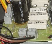
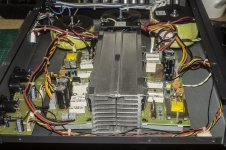
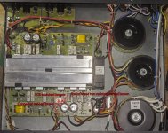
I'd have to get creative about how I'd mount larger caps, here's some pics that show the guts of the amp to give you an idea of the room there is in there.
Attachments

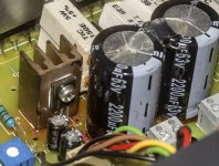

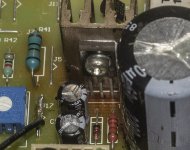
I'm not sure, but I suspect it isn't glue as where glue has been used, it is clear hot melt glue - look at the stuff on the top of the caps, would they use a totally different glue on the bottom of the caps? I doubt it. Another reason I'm not sure is that there is no bulging of the caps at the top and I'd expect the electrolyte to leak out of the top after the top had bulged and split.
Its glue...the glue on top is the same glue as on the bottom..just from heat its has gone brown, no need to replace as long as the measure good
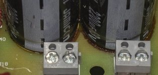
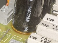
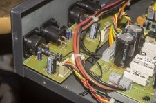
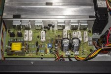
Flat, not bulged. However, there has definitely been a heat problem on one channel - the BD139 transistor with heatsink next to the caps has clearly got very hot, the PCB under it has turned brown from heat, this transistor is right next to the smoothing caps. There is more evidence of something having gone wrong in this area too as the end of the two ceramic resistors next to the BD139 and the caps has turned brown and there is some brown marking/gunk on the connector close by. The other channel doesn't have these overheating signs or brown spots, but does have some brown gunk around the base of the smoothing caps.
Attachments
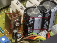
Flat, not bulged. However, there has definitely been a heat problem on one channel - the BD139 transistor with heatsink next to the caps has clearly got very hot, the PCB under it has turned brown from heat, this transistor is right next to the smoothing caps. There is more evidence of something having gone wrong in this area too as the end of the two ceramic resistors next to the BD139 and the caps has turned brown and there is some brown marking/gunk on the connector close by. The other channel doesn't have these overheating signs or brown spots, but does have some brown gunk around the base of the smoothing caps.
Ok, now I've seen it on the monitor rather than phone, with those photo's I'd tend to agree that they appear to have had an issue. The gunk also looks like it's corrosive on some of the spots.
I've seen some caps stuck at the base, although that's a double edged sword as the cap leads can pull/push due to thermal expansion during cycles.
I'm going to have to investigate deeper as when I tried to power it on a few minutes ago, nada. I need to check the fuses in the plug and in the amp (there is one in a compartment below the mains socket).
If the fuse in the amp has blown, I have to wonder if it was caused by a fault in the power supply section of the channel where the PCB is scorched brown.
If the amp is faulty, I might just return it for a refund as I already have a load of other repair jobs backlogged. I only paid 40 quid for it though with free shipping, and it's a pretty simple design so should be repairable even by a beginner like me.
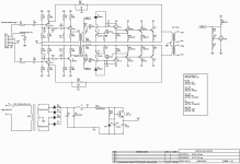
Here's the schematic and the specs, there are no exotic parts, just TIP35C output trannies, some TIP41C and BD/BC series trannies, very few caps, not a single opamp or IC anywhere, everything is discrete.
If the fuse in the amp has blown, I have to wonder if it was caused by a fault in the power supply section of the channel where the PCB is scorched brown.
If the amp is faulty, I might just return it for a refund as I already have a load of other repair jobs backlogged. I only paid 40 quid for it though with free shipping, and it's a pretty simple design so should be repairable even by a beginner like me.
Here's the schematic and the specs, there are no exotic parts, just TIP35C output trannies, some TIP41C and BD/BC series trannies, very few caps, not a single opamp or IC anywhere, everything is discrete.
Attachments

Drama over, it was the fuse in the plug, stuck a new one in and it powers up fine.
I posted the wrong spec sheet, the amp I have is the AMC+1202P, which replaced the AMS 1202P. The schematic is the correct one though.
Once the XLR connectors arrived in the post so I can make up the correct cables to connect it to my preamp, I'll see how it sounds, I suppose it will sound distorted and lacking in bass if the caps have indeed leaked their electrolyte.
- Home
- Amplifiers
- Power Supplies
- Replace leaking caps in Amp PSU stage