Lampie519 has the right sort of idea. Try inserting a 1K resistor in series with the gate of Q4. This will create an RC filter pole in conjunction with the gate terminal's parasitic capacitance, and is known as a 'gate stopper'. Solder the resistor close to the gate terminal of Q4.
Hi,
thank you for for your advise. I resolved my problem with a 1K gate stopper, but i don't understand why i have the problem with a cap in C7/C8 and no problem without cap in C7/C8.
thank you!Maxpou :RÉ
What did you find adjusting the resistor value? No change at all?
Another question: Is the output loaded (maybe a small resistor value in series will help (100 Ohm). This will increase the output Z a little but is good practice as it helps protecting the transistors agains short circuit and HF oscillation.
Hi Lampie
thank you for your advise too, i have modified my schematic and pcb to add a resistor in serie with my output.
Maxpou
Hi,
thank you for for your advise. I resolved my problem with a 1K gate stopper, but i don't understand why i have the problem with a cap in C7/C8 and no problem without cap in C7/C8.
thank you!Maxpou :RÉ
One guess is that without the bypass cap., 560R resistor R8 causes enough Miller capacitance on the drain to prevent the oscillation. However, having bypass cap. C7 in place prevents the Miller effect from increasing the parasitic capacitance seen by the gate, which works to slow down the device, just as adding the gate stopper resistor slows it down. Again, just a guess.
Last edited:
Hi,
i built this stage iv for the PCM1798 or COD from twisted pear audio....
Can we see the PCB layout?
One guess is that without the bypass cap., 560R resistor R8 causes enough Miller capacitance on the drain to prevent the oscillation. However, having bypass cap. C7 in place prevents the Miller effect from increasing the parasitic capacitance seen by the gate, which works to slow down the device, just as adding the gate stopper resistor slows it down. Again, just a guess.
Hi Ken,
thank you for explanation, very appreciated. Maxpou 😀
PCB
Hi extreme boky,
this is my PCB, comments are welcome.
thank you! Maxpou
Can we see the PCB layout?
Hi extreme boky,
this is my PCB, comments are welcome.
thank you! Maxpou
Attachments
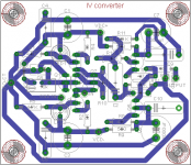
I think this can be cleaned up a bit...
Hi Lampie,
can you elaborate a little more?
Maxpou
- Home
- Source & Line
- Digital Line Level
- i/v stage problem