Hi,
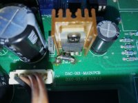
I was given this DAC a few years ago which was mucked around with by a friend, I had given up on it but, out of boredom, have decided to give it another go. The SS output works but the tube output stage was no longer working(fried?) and film caps and tube were removed. I suspect the culprit is a regular diode which was replaced by a Schottky. The regulator heatsink next to it gets hot to the point that it has changed color.
I have VERY basic DIY experience and am unable to interpret schematics.
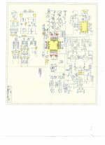
I'm inserting a picture of the diode and the DAC schematic hoping that someone could tell me what value/type diode needs to be in this location and if the regulator would need to be replaced and by what.
Thanks
I was given this DAC a few years ago which was mucked around with by a friend, I had given up on it but, out of boredom, have decided to give it another go. The SS output works but the tube output stage was no longer working(fried?) and film caps and tube were removed. I suspect the culprit is a regular diode which was replaced by a Schottky. The regulator heatsink next to it gets hot to the point that it has changed color.
I have VERY basic DIY experience and am unable to interpret schematics.
I'm inserting a picture of the diode and the DAC schematic hoping that someone could tell me what value/type diode needs to be in this location and if the regulator would need to be replaced and by what.
Thanks
Attachments
Last edited:
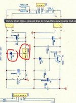
Your circuit diagram isn't very clear but the regulator and diode look to be a simple 12 volt arrangement (7812 type regulator... but look at the markings on what is actually fitted) that feeds the valve heaters. The diode simply 'adds' its voltage to the regulator output and so you get about 12.6 volts instead of 12v.
The diode is just a common 1N4001.
If the output of the regulator is at around 12.6 volts then your problems lie elsewhere. The output is on the right hand lead or pin.
The diode is just a common 1N4001.
If the output of the regulator is at around 12.6 volts then your problems lie elsewhere. The output is on the right hand lead or pin.
Attachments
Many thanks for taking the time,
I'm getting 10,07 volts output from the regulator which is an L7812V.
As I mentioned the original diode was replaced with a Schottky so I'm supposing a 1N4001 should be put back in that location.
Question 1: what would I need to do to get tube output to work again?
Question 2: what would I need to do if I wanted to forget about the tube output altogether but just prevent the regulator from getting red hot ?
Does the regulator get hot without the tube in place? The diode does not matter as it only rises the regulator above 12V. So even a wire can be used lowering the voltage to 12V. In case the regulator still gets hot it could be the capacitor next to it. If the ESR of this cap is too high the regulator starts oscillating.
Yes VERY HOT to the point that the heatsink has gone from black to gold over time.
That's what bothers me, I could live without the tube output but I don't want to go up in flames.
The capacitor is the original one installed by manufacturer.
Tube circuit film caps and tube itself have been removed.
Aren't diodes directional? I read something about reverse leakage when replacing regular diode with Schottky in wrong applications.
Last edited:
Then try to place small value caps as close as possible to the in and output pins of the regulator (to ground as a HF filter).
There is no load when the tube is removed (other option is that the cap is dead or even the regulator)?
There is no load when the tube is removed (other option is that the cap is dead or even the regulator)?
The above shows a nice simple supply that can be used for three or four 12AU7, 12AX7 (etc.) preamp valves. These draw about 150mA each from 12.6V supplies. The diode in series with the common lead of the 7812 regulator raises the voltage to very close to 12.6V. The in-built current limiting means that there is almost no heater surge current, so the valves just warm up gently. The filter capacitor needs to be large enough to ensure that the regulator has sufficient voltage to maintain regulation at all times. If it's too small, some ripple will appear on the DC output and may become audible. The second small cap is to ensure that the regulator doesn't oscillate.
Design Considerations - 2
Design Considerations - 2
Attachments
If I no longer want to use the tube output could I simply remove the regulator to avoid the heat issue?
The above shows a nice simple supply that can be used for three or four 12AU7, 12AX7 (etc.) preamp valves. These draw about 150mA each from 12.6V supplies. The diode in series with the common lead of the 7812 regulator raises the voltage to very close to 12.6V. The in-built current limiting means that there is almost no heater surge current, so the valves just warm up gently. The filter capacitor needs to be large enough to ensure that the regulator has sufficient voltage to maintain regulation at all times. If it's too small, some ripple will appear on the DC output and may become audible. The second small cap is to ensure that the regulator doesn't oscillate.
Design Considerations - 2
Sorry I'm really novice, you're losing me with the diagram.
BTW - I'm just recovering from Covid, my brain is a mess.
Yes, a diode has a direction. In this case it is "downwards" so almost all is passed from the positive side to ground, but as the diode has a threshold of 0.6V, the regulator will be regulating 12.6V instead of 12V exactly.
I see that you have a switch that bypasses the tubes if so wanted. (the schematic is a bit blurry).
In this case the tubes are not required and the regulator can be entirely be removed or unabled.
This can be done by removing the fuses of the tube power supply (low and high voltage power supply as non of them are required in this case).
In this case the tubes are not required and the regulator can be entirely be removed or unabled.
This can be done by removing the fuses of the tube power supply (low and high voltage power supply as non of them are required in this case).
Last edited:
OK I'll do that for now and decide later if I want to rebuild tube output.
Last question...so I just remove the regulator or anything else while I'm at it?
Thanks again
Last question...so I just remove the regulator or anything else while I'm at it?
Thanks again
Only the fuses of the regulator PCB.
I see that there is a connector (CN1) as well. Just unplug...that's all.
You can choose...
I see that there is a connector (CN1) as well. Just unplug...that's all.
You can choose...
Last edited:
Yes VERY HOT to the point that the heatsink has gone from black to gold over time.
There are gold coloured heatsinks around, it doesn't mean it changed colour from heat.
I've seen regulators fail many times. If it really does get hot without the valve in place then change the regulator and the diode and the electrolytic cap on the input to the regulator. That is the big one on the left of the reg on the diagram.
With the regulator removed, the diode bridge rectifier that supplies that rail should be cold. If it is not then change that as well.
- Home
- Source & Line
- Digital Source
- MiniMax DAC repair