Hi Gang,
VERY FIRST thread here on DIYAudio, and fairly newb-ish to circuit-building...so BE NICE TO ME! I'm actually pretty good at sourcing parts and building guitar stomp boxes etc from scratch using just the BOM and the PCB diagram, but I'm not educated yet and reading electrical schematics, or I'd be able to answer the following question myself:
I recently finished building Pete Millet's NuTube Buffer circuit, link here...
Nutube 6P1 Buffer PCB
...and am interesting in trying a couple of the mods he recommends. In particular, I'd like to try jumpering around the Mosfet output buffers in his circuit, as he states here...
I've tried communicating with Pete about stuff like this via email but I've had 50/50 luck on that and I'm sure he's a busy guy, so you folks are my next stop ;-)
VERY FIRST thread here on DIYAudio, and fairly newb-ish to circuit-building...so BE NICE TO ME! I'm actually pretty good at sourcing parts and building guitar stomp boxes etc from scratch using just the BOM and the PCB diagram, but I'm not educated yet and reading electrical schematics, or I'd be able to answer the following question myself:
I recently finished building Pete Millet's NuTube Buffer circuit, link here...
Nutube 6P1 Buffer PCB
...and am interesting in trying a couple of the mods he recommends. In particular, I'd like to try jumpering around the Mosfet output buffers in his circuit, as he states here...
"Since the 6P1 has relatively high plate resistance, I also put MOSFET followers at the outputs. If you are driving something that has high input impedance (> 100k or so), you can not populate the output buffers and jumper around them if you want."
So I guess I'm essentially looking for an idiot-proof answer along the lines of "start your jumper off of the R-whatever output hole and then finish it at C-whatever input hole" or thereabouts, so I literally know where to physically solder the jumper wire on the PCB...if that isn't too insanely f$%ing dumb for this forum.I've tried communicating with Pete about stuff like this via email but I've had 50/50 luck on that and I'm sure he's a busy guy, so you folks are my next stop ;-)
While I can see the schematic and the populated board before I commit myself I would like to see the actual copper runs on the reverse side .
At a guess and its a guess going by the components positions then the LEFT handside of =R8 & R9 when looking at the unpopulated picture and the diagram after that R8 is jumpered to the PLUS of C1 and R9 is jumpered to the PLUS of C8.
I hope you realise the consequences of the change of impedance by bypassing the fets used for impedance conversion to a much lower impedance output for driving a low impedance.
In other words what you are connecting the output to must have a higher INPUT impedance than the output impedance of the 6P1.
The buffers also help to isolate any fault condition from the tube but if that is what you want --so be it.
Hi Duncan,
Yes indeed as I am using this almost as a "stomp box" in a live guitar rig, I think the impedances will be fine. I will take a very clear photo of the backside tracers when I get home from work tonight and follow up on this thread as soon as I do!
Yes indeed as I am using this almost as a "stomp box" in a live guitar rig, I think the impedances will be fine. I will take a very clear photo of the backside tracers when I get home from work tonight and follow up on this thread as soon as I do!
While I can see the schematic and the populated board before I commit myself I would like to see the actual copper runs on the reverse side .
At a guess and its a guess going by the components positions then the LEFT handside of =R8 & R9 when looking at the unpopulated picture and the diagram after that R8 is jumpered to the PLUS of C1 and R9 is jumpered to the PLUS of C8.
I hope you realise the consequences of the change of impedance by bypassing the fets used for impedance conversion to a much lower impedance output for driving a low impedance.
In other words what you are connecting the output to must have a higher INPUT impedance than the output impedance of the 6P1.
The buffers also help to isolate any fault condition from the tube but if that is what you want --so be it.
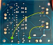
Hi Duncan,
To follow up from your request yesterday, here's a hi-res photo of the tracers on the back...
Attachments

Yes Greatmagnet exactly as I said the two thin tracers going to the gates of the fets jumper them to the positives of each output capacitor .
Yes Greatmagnet exactly as I said the two thin tracers going to the gates of the fets jumper them to the positives of each output capacitor .
Okay so I might be too dumb to know which pin on the fets are the gate pins (guessing middle), and I'm also guessing that the big electrolytics are the output caps specifically?
Check out my drawing below and tell me if the yellow lines are the right places to put the jumpers...