I'm working on a Califone portable cassette player, the type used in a school or a doctor's office back in 1980. 🙂
It can operate from batteries or the AC cord. That's where things get strange. This is what I'm seeing.
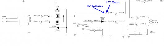
Battery power supply: approximately 9V DC (6 C batteries)
AC supply via hardwired cord: 15V DC
Both were measured exiting the power supply board and at the capstan motor.
Capstan Motor: Mabuchi EG-530AD-9F (working voltage is 6-11V). It appears to be the original motor (and is now dead).
The PS board is pretty simple, consisting of a full-wave rectifier setup and one cap. All of the diodes and the cap checked out ok when tested out of circuit. The transformer shows 13.4VAC across the secondaries.
I temporarily hooked up a different capstan motor, one rated at 12V, just to see how much of a voltage drop there might be from the motor being connected. It didn't result in an appreciable difference.
Of course, it's possible this is how the deck has been since new, but I want to make sure I'm not missing some other explanation.
It can operate from batteries or the AC cord. That's where things get strange. This is what I'm seeing.
Battery power supply: approximately 9V DC (6 C batteries)
AC supply via hardwired cord: 15V DC
Both were measured exiting the power supply board and at the capstan motor.
Capstan Motor: Mabuchi EG-530AD-9F (working voltage is 6-11V). It appears to be the original motor (and is now dead).
The PS board is pretty simple, consisting of a full-wave rectifier setup and one cap. All of the diodes and the cap checked out ok when tested out of circuit. The transformer shows 13.4VAC across the secondaries.
I temporarily hooked up a different capstan motor, one rated at 12V, just to see how much of a voltage drop there might be from the motor being connected. It didn't result in an appreciable difference.
Of course, it's possible this is how the deck has been since new, but I want to make sure I'm not missing some other explanation.
Attachments
What is the problem you are trying to solve?
The transformer voltage drops under load, when the motor and the sound output are working. At that point, it might be the voltages are within spec.
If in doubt, put a motor rated at a higher voltage, or put a drop resistor in series, when you put another motor.
The transformer voltage drops under load, when the motor and the sound output are working. At that point, it might be the voltages are within spec.
If in doubt, put a motor rated at a higher voltage, or put a drop resistor in series, when you put another motor.
What is the problem you are trying to solve?
The transformer voltage drops under load, when the motor and the sound output are working. At that point, it might be the voltages are within spec.
If in doubt, put a motor rated at a higher voltage, or put a drop resistor in series, when you put another motor.
Except I did swap in another motor, and the voltages did not drop to within spec--not even close.
I'm not concerned with how to reduce the voltage for the replacement motor. That's not the problem. I'd just like to make sure that there isn't an explanation for the voltage differences that I haven't thought of. Call it curiosity. 🙂
If we had sight of the rest of the power supply we could comment further but most DC motors, don't care what the voltage is as long as there is sufficient because there is a regulator onboard acting as the speed control.
Could the unit be a 230 volt model being used on 115v mains?
That voltage sounds a little on the high side tbh given that the battery supply is only 9v (plus a diode drop as well).
That voltage sounds a little on the high side tbh given that the battery supply is only 9v (plus a diode drop as well).
Mooly, don't you mean 110v model on 230volts.🙂
That would give a healthy 10volts ish.
That would give a healthy 10volts ish.
Last edited:
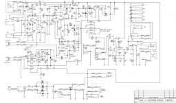
Jon: I've attached the full schematic. Let me know if the resolution is lacking. The original motor does have an internal speed regulator. Still, I assume Mabuchi gave an upper limit to the operating range for some reason.
Mooly: Hmmm. . . I hadn't considered this deck could be set up for a different mains voltage. But just checked the back label, and it does say 120V.
Mooly: Hmmm. . . I hadn't considered this deck could be set up for a different mains voltage. But just checked the back label, and it does say 120V.
Attachments
Better check the secondary voltage to be sure. I once connected 240V to a turntable that had a label saying 240V on the back. Seems someone configured it for 120V and the power supply stuff blew. Maybe the label did not peel so easy?
Mooly, don't you mean 110v model on 230volts.🙂
That would give a healthy 10volts ish.
Aye, something like that 🙂 It was to close to feeding time 😉
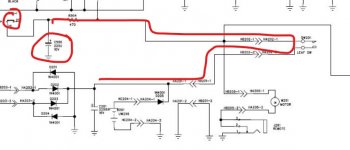
Does this cap say 10v (its a bit blurry). As shown and if the switch at the left is open then the cap will see the full supply via the 470 ohm. If it is 10v then that can't be right in seeing a 15 volt supply.
You're right--the schematic says 10V. But I checked the board, and the cap that's actually installed at C506 is a 220uF 25V.
Need to figure out how to share a higher res scan of this schematic. Try this.
Attachments
Last edited:
The motor will be governed, 9V or 15V may be the same speed.
If wall-power is available, 15V will play louder. If not, then battery will last longer at 9V.
I don't think it impossible it really will work either way.
If wall-power is available, 15V will play louder. If not, then battery will last longer at 9V.
I don't think it impossible it really will work either way.
So a bit of a mystery then (to me anyway) because although PRR is correct on the governed motor it is still being used way outside its maximum stated ratings.
Perhaps it is just the way it is and the dead motor is a result of the design running the motor at to high a voltage. The regulator in those things is normally just a two transistor circuit that senses back EMF from the motor as a means of maintaining speed as load increases. They were super common and readily interchangeable. All you needed to know was the voltage, the spin speed and CW or CCW.
I'm sure you know this but that hole on the back is for adjusting a trimmer to set the speed.
Ok, thanks PRR and Mooly. I appreciate the second look from everyone.
Sourcing a replacement motor that's spec'd to run from 6V (for the lower end of the battery power) to 15V and meets all the other necessary criteria, such as mounting requirements, shaft length, etc. is going to be a lot more difficult than just lowering the DC voltage. I suppose I could use a dropping resistor, but would it make more sense to add something like a 7809?
Sourcing a replacement motor that's spec'd to run from 6V (for the lower end of the battery power) to 15V and meets all the other necessary criteria, such as mounting requirements, shaft length, etc. is going to be a lot more difficult than just lowering the DC voltage. I suppose I could use a dropping resistor, but would it make more sense to add something like a 7809?
Don't overthink it. Adding a 7809 is going to mess up battery operation and it will take a bit more juggling to get the motor run on straight battery power when needed and via a 7809 when on mains (at least to run just the motor from 9v).
Just fit the same motor as was originally in there and hope for the best. It has lasted all this time...
Why not flick the backplate off the motor (they prize off) and try and deduce what the original failure mode is.
Just fit the same motor as was originally in there and hope for the best. It has lasted all this time...
Why not flick the backplate off the motor (they prize off) and try and deduce what the original failure mode is.
A voltage regulator can be used between C201 and junction D205. The batteries will not be affected as the diode will not conduct unless the voltage on that junction is lower then +8.3V.
Best regards, Frank
Best regards, Frank
That may be the most common motor ever made.
There is even a spec-sheet:
https://cdn.datasheetspdf.com/pdf-down/E/G/-/EG-530AD-9F_ETC.pdf
Shows that for light loads, 8.4V to 15V makes all the same speed.
-
Oh wait. That's the -2 version. Indeed you may have found the failure cause. Maybe the -9 model "works" at 15V but only for 30 years. There seem to be tons of these model motors online.
Attachments
Last edited:
- Home
- Source & Line
- Analogue Source
- Cassette Deck Power Supply Puzzler