Demia, I guess it can be set to do so.
I tried to test mine but it stopped communicating with my PC. Some driver issue again.
George
I tried to test mine but it stopped communicating with my PC. Some driver issue again.
George
Linkwitz & Perkins advocated the 5 cycle burst.
Cosine Burst
It should be easy enuff to generate on a computer.
dave
Cosine Burst
It should be easy enuff to generate on a computer.
dave
This waveform is continuous, right? I need it to be a burst of some cycles, followed by a blank period. I don't think that is possible this way. Probably is possibly offline.
Hi Jan
I have a similar generator (JDS6600) to the one George showed in a previous post. It seems to have a burst mode for channel 1, performing this exact function, which can be controlled both via software and the front panel controls. The number of cycles is also adjustable.
Could you set it to run one cycle of the burst and use the other channel to trigger the burst at arbitrary rates?
Hi Demian
On my JDS6600 the burst can be triggered either externally by a signal connected to the external input (Selectable AC or DC coupling) or internally from CH2. In the later mode the burst is triggered at a rate equal to the CH2 frequency setting. Triggering will happen regardless of the amplitude and offset settings of CH2 (its output can even be turned off). There is also a manual triggering mode in which the burst is triggered whenever you press the “OK” button on the front panel.
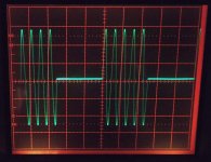
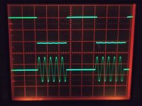
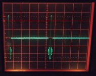
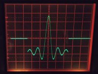
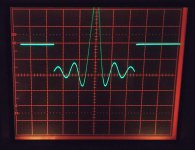
Here are some burst waveforms obtained in this mode. In all cases the burst (CH1) signal has a 1KHz frequency and 100mVpp amplitude and is triggered internally from (CH2) at a rate of 100Hz. There seems to be an anomaly in the sinc burst (see photo) due to the way that the sinc waveform is synthesized, which unfortunately cannot be counteracted by means of offset adjustment.
BTW ,when using the chopped mode on my oscilloscope to display both the burst and the CH2 output, I noticed an undulation on the square wave (it is evident in one of the photos) which is not present when the alternate mode is used. Does anyone have any idea why does this happen?
Regards
Marios
<edit> By hovering the mouse over the attached image, you can see the details of what they depict
Attachments
-
 Function Gen.jpg382.6 KB · Views: 109
 -
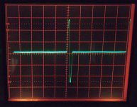 1KHz Sine 1cycle burst 100Hz repetition.jpg262.8 KB · Views: 100
 -
 1KHz Sine 5 cycle burst 100Hz repetition.jpg289.5 KB · Views: 103
 -
 1KHz sine 5cycle burst + CH2 output.jpg270.3 KB · Views: 97
 -
 1KHz sinc 1cycle burst 100Hz repetition.jpg272 KB · Views: 104
 -
 Zoomed 1KHz sinc 1cycle burst 100Hz repetition.jpg277.7 KB · Views: 72
Last edited:
Linkwitz & Perkins advocated the 5 cycle burst.
Cosine Burst
It should be easy enuff to generate on a computer.
dave
Dave, yes, I'm sure it is easy, but I prefer doing it on the test equipment. As shown in post # 3, that's exactly what I needed.
Jan
Hi Jan
I have a similar generator (JDS6600) to the one George showed in a previous post. It seems to have a burst mode for channel 1, performing this exact function, which can be controlled both via software and the front panel controls. The number of cycles is also adjustable.
Hi Demian
On my JDS6600 the burst can be triggered either externally by a signal connected to the external input (Selectable AC or DC coupling) or internally from CH2. In the later mode the burst is triggered at a rate equal to the CH2 frequency setting. Triggering will happen regardless of the amplitude and offset settings of CH2 (its output can even be turned off). There is also a manual triggering mode in which the burst is triggered whenever you press the “OK” button on the front panel.
Here are some burst waveforms obtained in this mode. In all cases the burst (CH1) signal has a 1KHz frequency and 100mVpp amplitude and is triggered internally from (CH2) at a rate of 100Hz. There seems to be an anomaly in the sinc burst (see photo) due to the way that the sinc waveform is synthesized, which unfortunately cannot be counteracted by means of offset adjustment.
BTW ,when using the chopped mode on my oscilloscope to display both the burst and the CH2 output, I noticed an undulation on the square wave (it is evident in one of the photos) which is not present when the alternate mode is used. Does anyone have any idea why does this happen?
Regards
Marios
Actually what you show in the 5th picture would be great if the mod. wave was properly around zero. That looks like a bug. And you say it doesn't react to a DC offset?
Jan
Actually what you show in the 5th picture would be great if the mod. wave was properly around zero. That looks like a bug. And you say it doesn't react to a DC offset?
Jan,
Its definitely a bug. Due to the way that the sinc waveform is generated in this generator, what actually comes out is the sinc function with a negative DC offset (I think it is Voffset = -Vpp/2 -Vmin of the waveform). When the waveform is continuous, this can be counteracted by means of a positive DC offset. However in burst mode, as the offset is constantly applied to the output and not only during the burst period, trying the same, results in the waveform shown in the attached photo.
(Scope coupling was set to DC and the GND reference, as in the previous photos, sits at the center horizontal graticule line.)
George,
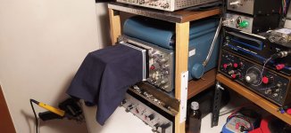
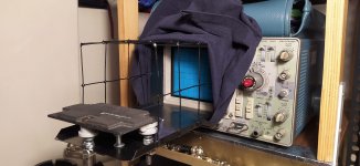
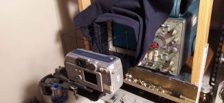
Thank you! Attached there is a photo of the apparatus used for photographing the scope screen.
Regards,
Marios
Attachments
Oh joy!
Can you do us the favor to raise the hood for we have the pleasure to blink at the inner construction?
Thanks in advance!
George
Can you do us the favor to raise the hood for we have the pleasure to blink at the inner construction?
Thanks in advance!
George

Most convienent is to buy a Tek scope camera for little money,
throw away the Polaroid and mount a digital camera fixture in
place.
throw away the Polaroid and mount a digital camera fixture in
place.
Excellent.
Thank you !
Most convienent is to buy a Tek scope camera for little money, throw away the Polaroid and mount a digital camera fixture in
place.
Actually, I thought about doing so, when I was searching for a way to take good photos of the scope screen. But, as I could not find a reasonably priced scope camera adapter at that time (I think, these dont show up that often in Europe), and having some pieces of scrap metal, I decided to try building something myself. I was inspired by the designs of the following website.
Herstellung einer selbstgemachten Kamera Halterung für ein Oszilloskop
Marios
I did try the Tek scope camera adapter thing but it was just too kludgy to use. My 7854 does digitize and I have the software so thats a good workaround but my Siglent does the same better. Now I just need to finish my Tek plug in adapter project to use all my plugins. Always something.
MKerk:
If you have a spare web cam, you might take a look at the projects linked in Convert Analog Oscilloscope into a DSO (aka webCam Oscilloscope)
If you have a spare web cam, you might take a look at the projects linked in Convert Analog Oscilloscope into a DSO (aka webCam Oscilloscope)
I did try the Tek scope camera adapter thing but it was just too kludgy to use. My 7854 does digitize and I have the software so thats a good workaround but my Siglent does the same better. Now I just need to finish my Tek plug in adapter project to use all my plugins. Always something.
I agree. Nothing can compare to how easy it is capturing waveforms with a digital scope. But you can enjoy this feature only if you have a DSO...
Maybe my two analogs would like to have a new friend in the future 🙂
The Tek plugin adapter sounds really interesting. I imagine it can pack even more functionality into a DSO.
MKerk:
If you have a spare web cam, you might take a look at the projects linked in Convert Analog Oscilloscope into a DSO (aka webCam Oscilloscope)
Hi JRE,
Thanks for your suggestion! I have tried them in the past. When using a webcam, the scope screen looked blurry. However, using my smartphone as a webcam, gave me much better results on both your software and the other one. If I remember correctly, the only thing I found as a drawback, on both, was the abscence of some fast time base settings (my Tek goes up to 1ns/div with the horizontal x10 magnifier on). But all in all, they 're pretty good.
Marios
Hi MKerk,
the timebase settings are in a configuration file. You can add any missing settings with a text editor. I can't go to a computer with the D43 software on it right now, else I'd give you an example.
Webcams usually have a fixed focus that is too short for reasonable use - but they are only fixed from the outside. Many have an adjustable focus once you get the front cover off.
I found that the Logitech C270 works really well.
-----
Wait. What? You used your phone as a webcam with the D43 software?
How did you do that?
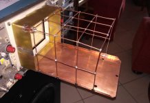
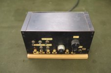
Here is a picture of the Shaped Tone-Burst Testing instrument which I built
40 years ago according to the Linkwitz article of post 10, figs. 11 and 12.
Together with a signal generator it fits the requirements of the first post.
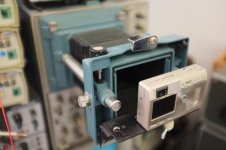
Second picture is the Tektronix digital camera fixture.
Usual bench distance of both is about 30 cm, so not too far off topic.
40 years ago according to the Linkwitz article of post 10, figs. 11 and 12.
Together with a signal generator it fits the requirements of the first post.
Second picture is the Tektronix digital camera fixture.
Usual bench distance of both is about 30 cm, so not too far off topic.
Attachments
- Home
- Design & Build
- Equipment & Tools
- shaped burst