You unsolder it from the switch, and you just solder together two wires which should be connected?
Besides, why do you have three wires there, two should be enough to turn it on? It looks to me you are shorting the plus to ground. No power supply likes it, smps can survive it, but still.
Which two shall be connected?
if you connect all 3, taking care of only middle one on pcb to be soldered on middle pin of switch section, then position of two remaining is irrelevant
and from picture, you got it right regarding "section" of switch
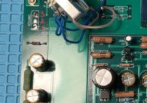
now- take a look at pcb and see which two pads for switch are connected to rest of circuit; toggle switch that you have short circ between these two ( use ohmmeter)
apply power and measure voltages at all caps in filter - black probe to GND, red probe to cap positive
write here
and from picture, you got it right regarding "section" of switch
now- take a look at pcb and see which two pads for switch are connected to rest of circuit; toggle switch that you have short circ between these two ( use ohmmeter)
apply power and measure voltages at all caps in filter - black probe to GND, red probe to cap positive
write here
Question, are there different kind of J113 4N35 and mosfet? I saw a few different ones on digikey. I followed the one on a spread sheet BOM from this forum. Did I ordered the wrong ones.
This was what I got:
https://www.digikey.com/en/products/detail/on-semiconductor/J113-D74Z/4743951
Also the 4N35
https://www.digikey.com/en/products/detail/vishay-semiconductor-opto-division/4N35/1738522
Mosfet
IRF610PBF Vishay Semiconductors | Mouser
This was what I got:
https://www.digikey.com/en/products/detail/on-semiconductor/J113-D74Z/4743951
Also the 4N35
https://www.digikey.com/en/products/detail/vishay-semiconductor-opto-division/4N35/1738522
Mosfet
IRF610PBF Vishay Semiconductors | Mouser
digikey is reliable source, what you ordered looks good
are you sure you did not put optocoupler wrong way around?
are you sure you did not put optocoupler wrong way around?
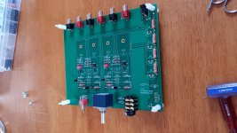
Started my my build
I started my build yesterday, made some decent progress and a ran into a couple minor issues as well.

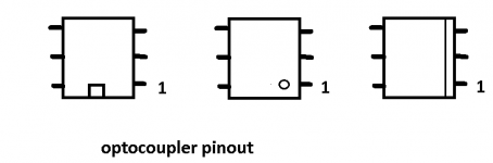
Things went smoothly until I got to the Q4 optocoupler, and just wasn't sure of the orientation. The one I selected didn't have the little dot over the #1 pin, I'm assuming when the text is oriented upwards, it's on the lower left. I'm hoping someone might be able to confirm this form me before I solder it in place.

The other issue I ran into is that I didn't pay close enough attention to the capacitors I ordered, and got everything with a 7.5mm lead spacing instead of 5mm. I can probably get a little creative to make them work, but I'm undecided if I just want to order some replacements.
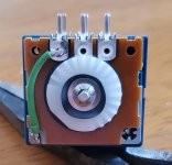
I'm not sure how many people this happened to, but I did see at at least one person who cooked a J113 with static when they touched the volume control after walking across the living room, and a suggestion of wrapping some wire around the shaft and soldering it to a ground. Since I still hadn't installed on the board yet, I'd take the opportunity to do it internally for a cleaner finish.

I started my build yesterday, made some decent progress and a ran into a couple minor issues as well.
Things went smoothly until I got to the Q4 optocoupler, and just wasn't sure of the orientation. The one I selected didn't have the little dot over the #1 pin, I'm assuming when the text is oriented upwards, it's on the lower left. I'm hoping someone might be able to confirm this form me before I solder it in place.
The other issue I ran into is that I didn't pay close enough attention to the capacitors I ordered, and got everything with a 7.5mm lead spacing instead of 5mm. I can probably get a little creative to make them work, but I'm undecided if I just want to order some replacements.
I'm not sure how many people this happened to, but I did see at at least one person who cooked a J113 with static when they touched the volume control after walking across the living room, and a suggestion of wrapping some wire around the shaft and soldering it to a ground. Since I still hadn't installed on the board yet, I'd take the opportunity to do it internally for a cleaner finish.
Attachments
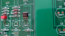
No dot on this one, just text. I'm assuming the "V" is replacing the dot, but I didn't know if anyone else could confirm.
If you look closely you will see a depressed strip on one edge of the chip. Orienting the chip with the strip on the bottom, pin 1 is at the lower left corner.
http://wb5rvz.org/common/locatingPin1
http://wb5rvz.org/common/locatingPin1
By the way, the LED I used was from a previous build left over green LED, not the blue specified in BOM. Does it make any difference in this application? I still can't get the build to work, can anyone enlighten me what I did wrong here?
Last edited:
The LED is just a light bulb saying the amp is on. I have a pink one in mine. (It’s a really neat pink with just a hint of purple...)
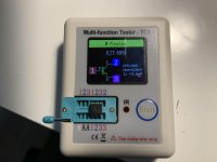
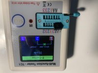
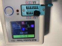
no, because 1,2,3 on top is identical to 1,2,3 on bottom, that is not the right way to test it
you could just test one side of the chip, which will id as led and then second side of the chip which id hard to predict, but would likely id as diode, because its photodiode
but what you are doing makes no sense
you shorted led side and photodiode side
you could just test one side of the chip, which will id as led and then second side of the chip which id hard to predict, but would likely id as diode, because its photodiode
but what you are doing makes no sense
you shorted led side and photodiode side
- Home
- Amplifiers
- Pass Labs
- Amp Camp Pre+Headphone Amp - ACP+