Hello,
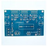
I bought 2 PCB to build 2 pa150 boards (see attached picture)
Every component comes from Mouser
Resistors for gain are 0,6W 0,1% 20kR and 1kR
47pF have been replaced by 8pF
Only one side is filled with 2 caps Panasonic 2200uF
22uF // 1uF are soldered directly at the rear pins of the 2 rails of the 3 LM3886
Thiele network have been added - soldered on the side of the speaker connector (not on PCB side)
The 3 pots has been well adjusted
10uf has been put for the input cap
PSU with toroid transformer 2x25V with secondaries decoupled with 100nF, 2 bridge rectifiers KBPC5010, 4x 22000uf caps, 2 5,6kR bleeding resistors.
I thought it was a pretty perfect setup, but no🙁. When there is no source connected to one PA150, it starts to oscillate - and I cannot know why 😕
Help !!!!
Many thanks,
Guillaume
Attachments
I could not see that this is Inverting.
In this mode, nothing at input, gain is unity instead of 20. Nearly any power amp will oscillate that way.
In this mode, nothing at input, gain is unity instead of 20. Nearly any power amp will oscillate that way.
I think it needs an opamp buffer on the input to stabilize it and cancel the inversion?
You can then lower the feedback network resistor values to improve the noise performance too. The 10k/200k values are only there so the input impedance isn't lower than the accepted minimum recommended impedance for an audio power amp. However paralleling 3 of them makes the input impedance actually 3k3, which is very low. And there's a (cargo-cult ?) 47k load resistor on the input too to lower the impedance a little bit further?
All in all using an inverting topology is problematic in a power amp.
Last edited:
I already replaced 10k/200k by 1k/20k to improve the noise performance.
Maybe I should have also lowered the 47k resistor to 4,7k ?
Maybe I should have also lowered the 47k resistor to 4,7k ?
So now your input impedance is somewhere around 330 ohms.
On top of that, the 50k pot is now just an open circuit as far as the amp is concerned when set higher than the feedback resistor.
Your output filter network is incorrect as well, and the 8pf cap is too small.
Basically the entire circuit is junk.
And Mark is right, making this an inverting topology is just wrong.
Get the LM3886 data sheet to see how it should be done.
Paralleling three LM3886 takes skill. Using the inverted input and having unity gain complicate that. Is this the normal design for a PA150?
I think it needs an opamp buffer on the input to stabilize it and cancel the inversion?....
Why stop there? We can add more complication.
The original design is revealed later. TWO of these were worked Bridge Mode, originally with a balanced-output chip. Which would supply the low source Z needed to be stable open-input. (And is yet more complication.)
When you lower the 200k to 20k you should increase 8pF to 80pF (75-100pF) proportionally.I already replaced 10k/200k by 1k/20k to improve the noise performance.
And it was pointed, that an inverting amp (LM3886/TDA7294) has to be used with a buffer (that is the main reason for oscillation I guess).
You'll want to add a smallish electrolytic cap as decoupling for the LM3886. National Semiconductor recommends a 10 uF per rail located by the LM3886 IC as a minimum.
You can improve it further from that. Read more here: Taming the LM3886 Chip Amplifier: Power Supply Decoupling – Neurochrome
Tom
You can improve it further from that. Read more here: Taming the LM3886 Chip Amplifier: Power Supply Decoupling – Neurochrome
Tom
Many thanks - I am going to do that 🙂When you lower the 200k to 20k you should increase 8pF to 80pF (75-100pF) proportionally.
And it was pointed, that an inverting amp (LM3886/TDA7294) has to be used with a buffer (that is the main reason for oscillation I guess).
Many thanks ! It is already done with a 22uF electrolytic cap and a 1uF X5R capYou'll want to add a smallish electrolytic cap as decoupling for the LM3886. National Semiconductor recommends a 10 uF per rail located by the LM3886 IC as a minimum.
You can improve it further from that. Read more here: Taming the LM3886 Chip Amplifier: Power Supply Decoupling – Neurochrome
Tom
Your website is my bedside reading 😉
Also the "designer" of this amp seems to have these oscillations, why else would he need to solder the decoupling caps onto the bottom.
Keep them there but remove C3,6,8.
the 8p can be increased to 15p but not much more
R8 change to 1 ohm 2W better 5W
Try all these steps 1 by 1 and see the outcome.
Keep them there but remove C3,6,8.
the 8p can be increased to 15p but not much more
R8 change to 1 ohm 2W better 5W
Try all these steps 1 by 1 and see the outcome.
Ignoring you have changed numerous components with a floating input and no RF filter it will suck in any RF or EMI that is going.
If the amps are in parallel the resistors should be 1% or better.
If the amps are in parallel the resistors should be 1% or better.
- Home
- Amplifiers
- Chip Amps
- LM3886 PA150 oscillates !!!