It is a passive twin-T followed by an amplifier. Based on my experience testing power amplifiers, a post-notch-filter amplifier is not necessary and even harmful, as it increases the noise floor considerably.The notch filter is a balanced implementation (or dual SE) based on Jansek.
In your measurements, you seem to be able to resolve signals down to about -140dbu, or -138dBV.
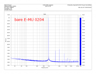
My measurements above show that a bare sound card without any external amplifiers achieves the noise floor about 10dB better.
Attachments
Last edited:
Very impressive!
The "discrete" input stage preceding the NE5534 is very interesting. Where can I learn more about it?
Many thanks!
Thank you. I found the original link here in a another LDO thread. That link now 404's but I managed to save a translated copy.
https://proaudiodesignforum.com/ima...ow_Distortion_Oscillator_Web_Page_Capture.pdf
Hi Mediatechnology
A well thought out and researched project - with very impressive results.
Thanks for sharing it
Do you know is anyone making a PCB available for the final circuit?
Regards
Mike
Thank you. A layout (in through hole) is on my to do list.
It is a passive twin-T followed by an amplifier. Based on my experience testing power amplifiers, a post-notch-filter amplifier is not necessary and even harmful, as it increases the noise floor considerably.
In your measurements, you seem to be able to resolve signals down to about -140dbu, or -138dBV.
My measurements above show that a bare sound card without any external amplifiers achieves the noise floor about 10dB better.
The oscillator output level in my example is +20 dBu.
Last edited:
I've been working on a low distortion oscillator
The fact that the fundamental before the notch has a high level attests to the quality of the oscillator. Designing a low distortion oscillator is a great achievement. Yours seems to be on par with some good designs out there, so congratulations.The oscillator output level in my example is +20 dBu.
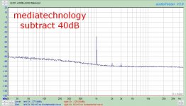
My point, however, is different. In order to measure low distortion with a sound card, you need to be able to see the harmonics on the FFT graph. Using a passive notch filter to suppress the fundamental is one of the possible ways to achieve that. By using an extra amplifier after the filter, you are giving away 10dB of resolution for no apparent reason. With the amplifier, you can see peaks at -138dBV; without it, at -148dbV. In other words, you should be able to see more detail by dropping that amplifier and keeping just the passive twin-T.
Last edited:
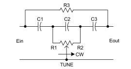
There is another option for the topology of a passive notch filter - the Hall network:

Like the twin-T, the Hall network requires three capacitors and three resistors. Unlike the twin-T, the capacitors are identical. However, the best feature is that the Hall network can be made tunable. The details can be found in the attached article.
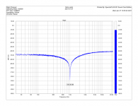
With unmatched capacitors and with each resistor made of three E24 resistors in parallel, about 80dB rejection of the fundamental can easily be achieved:
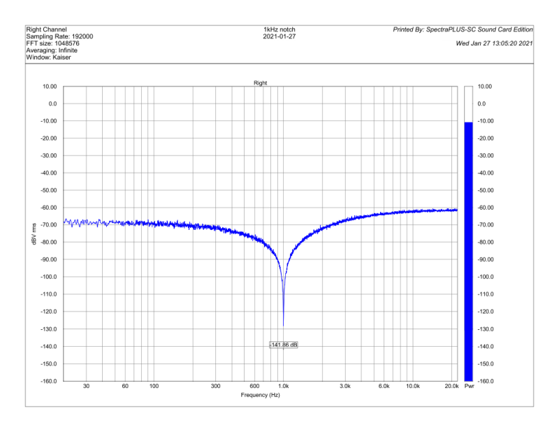
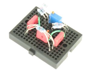
Disclosure: in the past, I organized a group buy of PCBs for a low distortion notch filter designed by Samuel Groner, using this topology. The interest was so high that I did not have a single board left to myself. The above results are from a filter built on a solderless breadboard:
Like the twin-T, the Hall network requires three capacitors and three resistors. Unlike the twin-T, the capacitors are identical. However, the best feature is that the Hall network can be made tunable. The details can be found in the attached article.
With unmatched capacitors and with each resistor made of three E24 resistors in parallel, about 80dB rejection of the fundamental can easily be achieved:
Disclosure: in the past, I organized a group buy of PCBs for a low distortion notch filter designed by Samuel Groner, using this topology. The interest was so high that I did not have a single board left to myself. The above results are from a filter built on a solderless breadboard:
Attachments

Last edited:
Thank you. I found the original link here in a another LDO thread. That link now 404's but I managed to save a translated copy.
https://proaudiodesignforum.com/ima...ow_Distortion_Oscillator_Web_Page_Capture.pdf
Thanks Media. I also found a bit more in your earlier post:
Super Low Distortion Ultra Pure Audio Oscillators Revisited - Page 5 - Pro Audio Design Forum
Last edited:
[QUOTE Thank you. A layout (in through hole) is on my to do list.[/QUOTE]
In which case, I would like to put my name for 2 if I may.
Kind regards
Mike
In which case, I would like to put my name for 2 if I may.
Kind regards
Mike
With unmatched capacitors and with each resistor made of three E24 resistors in parallel, about 80dB rejection of the fundamental can easily be achieved:
Hello, alexcp~
The Hall network you shared is very interesting, thank you!
I want to know whether the Hall network passive notch filter in the example will increase the background noise? Is it possible to choose a lower resistance value in the trap to reduce noise, do they have a significant effect?
Another question. I have an old-fashioned distortion meter. The distortion tester has an input impedance of 100KΩ. When using a 20K+20K resistor as a voltage divider to reduce the signal source voltage, I observed a very significant distortion deterioration. Passive traps often have higher output impedance. If the voltage follower is not used, will the passive notch filter lose its use value?
Wish you all the best🙂
- Possibly it wasn't a distortion deterioration but an increased noise floor?Another question. I have an old-fashioned distortion meter. The distortion tester has an input impedance of 100KΩ. When using a 20K+20K resistor as a voltage divider to reduce the signal source voltage, I observed a very significant distortion deterioration.
The noise has indeed deteriorated, but the distortion has also deteriorated.
I tested THD and THD+N respectively, and both deteriorated.
Perhaps the increase in source impedance has caused a series of complex effects, and ultimately caused deterioration.
I tested THD and THD+N respectively, and both deteriorated.
Perhaps the increase in source impedance has caused a series of complex effects, and ultimately caused deterioration.
There is a doc. "Distortion and source impedance in JFET-input op amps
By John Caldwell"
Though hard to tell if it's related w/o seen THD meter's drawings.
By John Caldwell"
Though hard to tell if it's related w/o seen THD meter's drawings.
That's a common effect usually caused by the common mode distortion. Drive an amplifier circuit with 10kOhm and you will see distortion that typically rises with frequency at 20dB/decade. It doesn’t matter whether it is JFETs or bipolar, op amp or tubes - most amplifier circuits have non-linear input impedance which causes this.When using a 20K+20K resistor as a voltage divider to reduce the signal source voltage, I observed a very significant distortion deterioration.
A passive notch filter has high output impedance - in my builds, 10s of kOhms - and thus requires some measures, such as a buffer, to prevent common mode distortion.
May I ask you to post the doc or a link to it?There is a doc. "Distortion and source impedance in JFET-input op amps by John Caldwell"
also...Analog Design Journal archive: https://www.ti.com/lit/sg/slyt778/slyt778.pdf
As noted in the TI Analog Applications Journal 2014 4Q note in thread post above....
The SOI JFET input OPA1641/1642/1644 looks like a nice choice for high input impedance and low harmonic distortion non inverting applications, due to minimal voltage dependent (varactor) common mode capacitance on the differential pair & tail current.
The CMOS LM1656 might be an interesting op amp to compare for high input impedance and low harmonic distortion non inverting applications. The voltage dependent (varactor) common mode capacitance on the differential pair & tail current might (?) not be as low as the SOI JFET input OPA1642.
I now can announce I have a solution to that exact problem, extracting distortion and other ill effects that are way below the distortion (and noise) floor of the test rig (DAC-->ADC), with the feature that any test signal can be used (including music ;-) Also, the DUT does not have to be modified for higher noise gain (not possible anyway with more elaborate composite amps with higher order feedback).I am starting this thread to discuss the techniques of measuring low distortion levels, say, 0.000 010% (10u%) with inexpensive equipment such a sound card.
The problem of measuring such low distortion levels came up in connection with developing an audio power amplifier with the loop gain of 100dB@20kHz and with the correspondingly low distortion levels even at the high end of the audio spectrum.
What I don't want to discuss is choosing (or making) a better sound card or a low distortion oscillator. These topics are very interesting but are being discussed in a number of other threads which I don't want to duplicate. Thank you for keeping these out of this thread.
Instead, I want to focus on the problems that arise when easily available equipment is used for assessing the distortion performance of highly linear amplifiers and on the way to address those problems.
So far, several topics are emerging:
- Properly conditioning the DAC output signal and the ADC input signal
- Using (passive) filters to filter out the distortion of the DAC and to remove the fundamental from the ADC input
- Subtracting the scaled output signal from phase corrected input in either analog or digital domain
- Increasing the noise gain of the device-under-test to increase distortion to a measurable level and estimating from it the distortion under normal conditions
- Correcting nonlinearities of the DAC and ADC in the digital domain (the work of phofman)
It's based on subtractive analysis with a lot of tweaks to make it stable and reliable, the import thing being to cancel out any small linear differences (simple mag&phase frequency response differences, including time delay) so that direct subtraction becomes possible and gives below -130dB RMS Nulls for linear differences whereas any nonlinear residuals are much larger. The other corner stone is the use of heavy time-domain averaging to reduce uncorrelated noise and gain drifts etc (just the DAC-->ADC alone -- RME ADI-2 Pro FSR in my case -- has enough dynamic gain drift, among other drifts) that makes this averaging necessary.
It's relative technique, always a comparison of a DUT against a know reference... but that is just a piece of short cable from DAC out to ADC in, in the simplest case. DAC out and ADC in of course must see the same levels and load/source impedance to avoid introducing unknowns. For the same reason, larger frequency response changes should be avoided or approximately compensated for in the "reference" setting.
For some preliminary results, see here Beta-test: DeltaWave Null Comparison software | Page 27 | Audio Science Review (ASR) Forum, and a few of my preceding posts in that thread.
I've also now been able to measure effective "cable distortion" for a long crappy cable vs short jumper cable for the first time (root cause to be examined).
I'm still refining and stabilizing the technique, identifying the critical variables, so that I can eventually publish a paper (+ some required software I wrote) so everybody may try it (and backup any typical results I'm getting). Before that, I will post some latest results... the big drawback is that the process is really time-consuming mostly from the huge amount of averaging but also because the process steps are still all manual atm.
Very true! In order to keep the ADC levels exactly equal, I've automated this process by means of a dual 10 turn potentiometer, driven by stepper motor. See: this link[...]
It's relative technique, always a comparison of a DUT against a know reference... [...] DAC out and ADC in of course must see the same levels and load/source impedance to avoid introducing unknowns.
[...]
In this way, distortion measurements were possible down to ca. -170dB (see also this link).
Cheers,
E.
Ha, I see we went through same pains and found the same solutions ;-)Very true! In order to keep the ADC levels exactly equal, I've automated this process by means of a dual 10 turn potentiometer, driven by stepper motor. See: this link
In this way, distortion measurements were possible down to ca. -170dB (see also this link).
Cheers,
E.
Notably the interleaving of DUT and Reference during averaging to reduce the drift (1/f-noise) -induced residual as well as to lower the general noise. And then compensate the impact of the linear transfer function differences of the DUT vs Reference.
I found interleaving awkward in the end as one has to take care of settling, relay switching time / bouncing which takes a significant percentage of the total time, additional hardware needed for the switching and to sync it, so I thought about a way to avoid it altogether.
Which was, boiling down the concept:
- most important, embed the sweep in the recorded signal itself for later extraction of the IR of the transfer function (this of course also decreases the "net to gross payload ratio" as the sweep needs to be some length for higher resolution and low noise).
- record DUT and reference, block-average at least 100 times (1000 is better, another 10dB reduction, but then a 35second test signal (including the sweep) amounts to 10hours of recording, puh... 10k+ averages are impractical for this kind of test with embedded sweep.
- cross-apply the IR's to the recordings --> linear stuff gets cancelled, both now have the same transfer function (basically the squared function as TF's are very close to start with). The cross-convolution yields very symmetric processing and it avoids having to divide IR's so that B*TF(A)/TF(B) - A == 0, rather I do B*TF(A) - A*TF(B) == 0
- subtract, analyze
It is stable in that I see no change in residual baseline & noise floor when comparing two recordings of the same DUT, even when spaced apart several days. The RME has to be fully warmed up but it is on 24/7 anyway...
The beauty of it is that it all works in the time-domain so it is possible to examine termal tails, any form of compression etc, not just steady-state simple signals. Plus the asset of making the magnified total distortion audible in what it does to the music, the character of the total error terms.
Averaging has its drawbacks, things like excess noise of resistors etc is hard to catch but I'm working on how to peel this kind of errors (somewhat signal-correlated noise) as well... looking at the time-envelope of noise vs signal, something along these lines...
Last edited:
Hi KSTR,Ha, I see we went through same pains and found the same solutions ;-)
Notably the interleaving of DUT and Reference during averaging to reduce the drift (1/f-noise) -induced residual as well as to lower the general noise. And then compensate the impact of the linear transfer function differences of the DUT vs Reference.
I found interleaving awkward in the end as one has to take care of settling, relay switching time / bouncing which takes a significant percentage of the total time, additional hardware needed for the switching and to sync it, .........
[...]
By using mercury wetted reed relays for the multiplexer, I didn't have serious issues with switching time and bouncing. It reduced the "play load" by a mere 2%.
But that's not all. Apart from measuring the distortion of the Ref and DUT on a interleaving basis, I also measured the frequency and phase response of both of them (also interleaving). That reduced the "play load" by another 50%. In other words, that doubles the total measuring time, which was already quite long (1 hour or so in order to average out the noise sufficiently).
Now, almost 10 years later, I have abandoned this route and try to get the same measurement floor (-170dB) by using only passive twin T filters. Way more simple and less expensive. The only draw back of this approach is that you need to adapt the filters each time you change the fundamental frequency (measuring the distortion of an amp at only one frequency is not enough, at least at 20Hz, 1kHz and 20kHz).
BTW, what measurement floor you are aiming for?
Cheers,
E.
- Home
- Design & Build
- Equipment & Tools
- Measuring low distortion levels with a sound card