I've seen this article:
r-tec2102_(07)superT-ULD-amp_KurodaT.pdf - Google Drive
taken from this site:
記事録 2021-2022
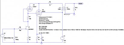
and I decided to simulate the circuit at page 109, because I already have a SE pcb that can be modded to adopt that design.
These are the results of the hybrid SE amp with EL84 at 4.3 Wrms:
r-tec2102_(07)superT-ULD-amp_KurodaT.pdf - Google Drive
taken from this site:
記事録 2021-2022
and I decided to simulate the circuit at page 109, because I already have a SE pcb that can be modded to adopt that design.
These are the results of the hybrid SE amp with EL84 at 4.3 Wrms:
Code:
Harmonic	Frequency	 Fourier 	Normalized	 Phase  	Normalized
 Number 	  [Hz]   	Component	 Component	[degree]	Phase [deg]
    1   	1.000e+03	8.272e+00	1.000e+00	   -0.52°	    0.00°
    2   	2.000e+03	1.318e-01	1.593e-02	  -90.87°	  -90.35°
    3   	3.000e+03	3.921e-02	4.739e-03	    0.15°	    0.67°
    4   	4.000e+03	1.057e-02	1.278e-03	   89.51°	   90.03°
    5   	5.000e+03	4.913e-03	5.939e-04	 -175.41°	 -174.89°
    6   	6.000e+03	2.385e-03	2.884e-04	  -95.19°	  -94.67°
    7   	7.000e+03	2.314e-03	2.797e-04	    7.19°	    7.71°
    8   	8.000e+03	3.984e-04	4.816e-05	  -95.69°	  -95.17°
    9   	9.000e+03	5.549e-04	6.707e-05	  178.40°	  178.92°
Total Harmonic Distortion: 1.668950%(1.669417%)
Attachments
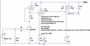
This is a version with EL34 at 10.5 Wrms:
Code:
Harmonic	Frequency	 Fourier 	Normalized	 Phase  	Normalized
 Number 	  [Hz]   	Component	 Component	[degree]	Phase [deg]
    1   	1.000e+03	1.294e+01	1.000e+00	   -0.40°	    0.00°
    2   	2.000e+03	3.188e-01	2.463e-02	  -90.80°	  -90.40°
    3   	3.000e+03	1.355e-01	1.047e-02	   -0.62°	   -0.21°
    4   	4.000e+03	4.104e-02	3.171e-03	   88.63°	   89.03°
    5   	5.000e+03	3.165e-02	2.446e-03	 -179.68°	 -179.28°
    6   	6.000e+03	1.520e-02	1.175e-03	  -94.37°	  -93.97°
    7   	7.000e+03	1.282e-02	9.909e-04	    0.54°	    0.94°
    8   	8.000e+03	4.709e-03	3.639e-04	   83.68°	   84.09°
    9   	9.000e+03	3.512e-03	2.713e-04	  164.98°	  165.39°
Total Harmonic Distortion: 2.711032%(2.711414%)
Attachments
.....
These are the results of the hybrid SE amp with EL84 at 4.3 Wrms
Total Harmonic Distortion: 1.668950%(1.669417%)
Roberto,
Thanks for your post.
I’m watching your simulations because you do interesting stuff, but also to help me learn LTspice, and I have a question regarding the primary inductance of the output transformer. The value in the schematic seems high to me for a SE transformer, or is the value in the simulation some multiple of a real life transformer?
Hi Francois,
I don't have a good model for OPTs, so I just used an high value to consider it out of the game. More realistically it should be 50 H instead of 150 H, and the capacitor should be 100 uF instead of 10 uF.
I don't have a good model for OPTs, so I just used an high value to consider it out of the game. More realistically it should be 50 H instead of 150 H, and the capacitor should be 100 uF instead of 10 uF.
Neither I to give more articulated answers by now! 🙂
There are probably alot of possible improvements on my adaptation for the EL34, but it is at least promising! It is a nice way to give local feedback to the power tube, improve distortion and damping, plus avoid coupling and (some) supply caps at the same time: one single supply node is enough for the whole channel.
This can make the whole amp smaller, cheaper and easier to build.
Hi, here it is a KT88 version with the following results at 18.6 Wrms:
Code:
Harmonic	Frequency	 Fourier 	Normalized	 Phase  	Normalized
 Number 	  [Hz]   	Component	 Component	[degree]	Phase [deg]
    1   	1.000e+03	1.722e+01	1.000e+00	   -0.24°	    0.00°
    2   	2.000e+03	3.598e-01	2.089e-02	  -91.15°	  -90.91°
    3   	3.000e+03	2.633e-01	1.529e-02	    0.04°	    0.29°
    4   	4.000e+03	3.509e-02	2.037e-03	   83.51°	   83.75°
    5   	5.000e+03	6.225e-02	3.614e-03	 -179.11°	 -178.86°
    6   	6.000e+03	1.342e-02	7.792e-04	  -98.18°	  -97.93°
    7   	7.000e+03	2.327e-02	1.351e-03	    0.08°	    0.32°
    8   	8.000e+03	2.522e-03	1.465e-04	   72.67°	   72.91°
    9   	9.000e+03	7.891e-03	4.582e-04	  179.25°	  179.49°
Total Harmonic Distortion: 2.626568%(2.626863%)
Attachments
I tried to see where I might buy 2SK30A transistors and found that they are “unobtanium”, except for potentially questionable sources on eBay. Could you specify a different jfet that is currently being made?
The LSK189 grade A has very close characteristic to a 2SK30A. Nacsemi seems to have them in stock @ LSK189-TO-92 | LINEAR SYSTEMS | NAC Semi.
Hi, here it is a KT88 version with the following results at 18.6 Wrms:
18W .... khmmm....
Are you sure that you use proper operating point?
Attachments

@Francois: I've done simulations with original design and I've bought some questionable ones, then I'll try with equivalents.
@indra1: thanks for the suggestion!
@euro21: I've used the "alt+click" command on the KT88 to show its dissipated power, then the "ctrl+click" command on the plot of the dissipated power to show its average value, and it tells me around 36 W. How can it be wrong?
@indra1: thanks for the suggestion!
@euro21: I've used the "alt+click" command on the KT88 to show its dissipated power, then the "ctrl+click" command on the plot of the dissipated power to show its average value, and it tells me around 36 W. How can it be wrong?
Try to run "DC op pnt" command to see static (a,c, g) voltage and current amounts.
Are you sure, that tube model is correct?
Are you sure, that tube model is correct?
Single Ended KT88 with 50% efficiency.
Wow!
That is a miracle.
Or, is it measured using square waves?
Wow!
That is a miracle.
Or, is it measured using square waves?
Francois G,
You are correct. I was unkind.
I used to want to use JFETs in Vacuum Tube amplifiers.
But I found that they often have a very large spread of specifications.
Example, the 2SK30A
IDSS ranges from 0.3mA to 6.5 mA (Drain current, with the gate at 0V with respect to the Source, and Drain to Source voltage 10V).
Gate cutoff (for 100uA ID) ranges from -0.4V to -5.0V (with the Drain to Source voltage 10V).
It is very hard to design with such a large spread of parameters.
The 2SK30A is expected to work at 10V Drain to Source.
I think that any vacuum tubes that have that large of a spread, need to be thrown into the garbage.
Imagine a 12AX7 that has 100uA plate current when the grid ranges anywhere from -0.4V to -5.0V.
Imagine a 12AX7 that has 0.3mA to 6.5mA with the grid at 0 Volts.
True, the 12AX7 is not going to work predictably at only 10V on the plate.
But for more realistic fixed plate voltages, say 90V, 150V, or 250V, it will not have nearly as wide a spread of parameters as are listed above.
Last edited:
@euro21: thanks for the suggestion, I will try that command. I will report here the model I use.
@6A3sUMMER: I should have noticed that, indeed. Concerning the second post, matching jfets is mandatory as you know, and the Idss ranges "only" from 1.2 to 3.0 mA as it is specified the suffix "A". https://datasheet.octopart.com/2SK30A-Toshiba-datasheet-101654.pdf
@Francois: thank you!
@6A3sUMMER: I should have noticed that, indeed. Concerning the second post, matching jfets is mandatory as you know, and the Idss ranges "only" from 1.2 to 3.0 mA as it is specified the suffix "A". https://datasheet.octopart.com/2SK30A-Toshiba-datasheet-101654.pdf
@Francois: thank you!
Interesting discussion... But is it worth having a FET input and tube output - just to get rid of a coupling cap between the 12AX7 front end and the output tube? How does this compare to a SRPP 12AX7 R-C coupled to the output tube?
Hybrids are normally done with tube amplification and MOSFET or FET outputs. P & N type so we don't need output cap...
Many things can be built of course - each with it's own sound. So by all means, crack on with this one. It is a hobby after all. Thanks for sharing.
D.
Hybrids are normally done with tube amplification and MOSFET or FET outputs. P & N type so we don't need output cap...
Many things can be built of course - each with it's own sound. So by all means, crack on with this one. It is a hobby after all. Thanks for sharing.
D.
Hi vilfort,
I already have an hybrid PP amp (you can see reference here: improvements on 12AX7 12AT7 EL34 schematic? ) and also another user of this forum developed his own version of that amp ( 100W + 100W amp to share ) and I have to say I'm happy with it as it is now. Everything is improvable, most probably this won't be the best sounding amp ever built, but as a newbie I consider the design interesting.
I'll try to design a PP version of it, doubling the circuit and adding a CCS on the sources of the jfets.
6A3sUMMER
How did you calculate to get 50% ?
The values in the schematic show approximately 55 watts plate dissipation.
Steve
How did you calculate to get 50% ?
The values in the schematic show approximately 55 watts plate dissipation.
Steve
- Home
- Amplifiers
- Tubes / Valves
- Another hybrid design, this time SE