In practice with 100-220uF for Cadj (such as VRDN) the PSRR is in the 75-80dB ballpark.
Or you can just check the measurements from few posts back from my LM337 pcb, and you'll see the denoiser at the -115dB mark.
Or you can just check the measurements from few posts back from my LM337 pcb, and you'll see the denoiser at the -115dB mark.
Last edited:
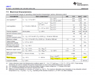
No surprise, Iq of bc327 is higher at 21v out - higher effective gm.Noise at 7 V is measured to be 14 nV/rtHz. 😱
Noise at 21 V is 4.6 nV/rtHz. 🙂
The PSRR I got also seems to be similar to what the LTSpice sim predicts, using the exact parts and values, with the LM337 LTSpice model from TI's website, and I also used the TI LM337 regulator on the pcb I measured.
-91dB for PSRR is not a figure to boast with really for a denoiser.
edit: that's right about what I got while also measuring my SMD pcb for SMD LM337, still from TI, around the -115dB area. I will publish the measurements for the SMD board tomorrow.
-91dB for PSRR is not a figure to boast with really for a denoiser.
edit: that's right about what I got while also measuring my SMD pcb for SMD LM337, still from TI, around the -115dB area. I will publish the measurements for the SMD board tomorrow.
Attachments
Last edited:
You can also clearly see in the first measurements RickRay made before he calibrated his gear.
VRDN: bipolar regulator PCB for line level ckts: ±11V to ±20V @ 1.5A with "De-Noiser"
At least on the positive regulator which was working you can see only a 15dB decrease in ripple. Which is what his latest measurements show. 91dB-15dB lands at 76dB (maybe 79dB for positive rail). Which is thereabouts for Cadj.
You're basically running with half a denoiser's worth of PSRR. That doesn't really do any justice to the denoiser circuit, implemented this way.
Maybe the PSRR difference is more now that RickRay calibrated his gear but I doubt it. I think it's in the same 15dB improvement area, which is, depending on layout, either half either less than half of the denoiser performance.
And this is consistent with my previous statements. If the denoiser is stable you get the low noise, but if the design is not optimal then PSRR suffers.
Last edited:
Before jumping into any conclusions regarding RickRay's PSRR measurements you should first check how much ripple his LNA has. E.g. at 50Hz the output ripple seems to come from the LNA as the PSRR@50Hz is only about 45dB.
For a such consideration one must be reasonable in the first place. 🙄
As RickRay is using very low input ripple voltage (-45 dBV), there is very likely that 120 Hz from the environment is adding to the output measurement at the -140 dBV levels.
Another point is that measurement at 21V will return above 100 dB PSRR results due to the increase of AC gain in the denoiser circuit, as Elvee explained.
Third point is that using PSRR of the SMD LM chip version based denoiser as an argument is wrong, as SMD variant has 16 dB higher default PRSR then it’s through hole counterpart to start with.
Last edited:
That is not really due to the SMD version. LM337N is I think a better binned version of the normal LM337. It's also more expensive than regular LM337. My previous measurement has been done with LM337N for THT version as well.
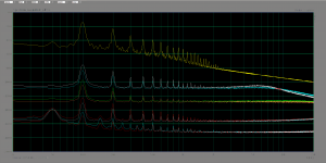
But I made another measurement for a Farichild LM337 which should represent regular LM337 performance.
Still, the denoiser comes out at -108.3dB. Still pretty far from -91dB. Do you think the 17dB between them is due to various issues you mention like input ripple etc?
Isn't it more possible at this point that it's due to the pcb layout?
I put the Fairchild LM337 measurements over TI's LM337N. In the archive I added the measurements for the Fairchild LM337 with cursor at points of measurement.
Attachments
Last edited:
@bohrok2610 very good point, I do plan to implement the dienoiser in my LNA, but parts won't be here till late next week. In the meantime, I'll look inti powering it with 9V batteries. That would be a great measurement to compare how noise in LNA effects measurements
@RickRay
Was a ring around Focusrite gain control lit red while you were measuring ripple at the input side?
At -45 dBV, I expect it was and that means Focusrite was clipping and you were not getting correct reading but lower than actual. Correspondingly, calculated PSRR turns out smaller than it is.
It is better to measure input ripple with voltmeter or oscilloscope.
Another possible issue is level of EMI. At -140 dBV, any transformer in vicinity is clearly present as 60 Hz + 120 Hz harmonic in the fft graph. Switch off any transformers you can at your workplace. I can measure transformer placed in the thin steel box under my working desk.
Disconnect VRDN from transformer but leave transformer on. Take measurement on powered down VRDN. If 60 Hz and 120 Hz readings are not 20 or more dB below your VRDN readings, then they affect measurement.
If the ADC goes into protection then it grounds the input and you get the lowest noisefloor, which is of the ADC grounded internally. Overloading the ADC input is pretty clear on the graph.
Also measuring the input ripple with the oscilloscope would be good if we had an output ripple reading also with the oscilloscope.
RickRay's LNA is the same that I have. It's a pcb I designed around a mc preamp circuit from Douglas Self.
Wouldn't the 120Hz harmonic from 60Hz mains interfere with the VRDN's output ripple if the 60Hz mains would be higher as amplitude, than the 120Hz ripple? Could the 120Hz harmonic be higher than the 60Hz fundamental on the output of the VRDN?
Also it would be pretty simple to preserve the differential measurement for input/output ripple. All RickRay has to do is to remove the input capacitors and install a single 470uF or something like that. It would offer a better view with the differential measurement between input and output with the same measurement tool.
I calibrated with LNA connected and FS sine rms voltage set to .001.
Took output readings. Then changed FS sine rms voltage to 1.0, recheck calibration without LNA.
Took input readings.
Focusrite was barely blinking green.
Useing scope or meter for input and spectrum for output will exagerate the final PSSR.
The scope and meter both take an average reading over the bandwidth, ther readings will always be way lower than reading from spectrum analyzer reading 120Hz bin.
Need to use same method to read input and output to be accurate.
It's rather simple to increase all levels so you reduce any noise pickup interference with the low level measurement. Remove all input capacitors and use around 220uF to 470uF value, only one cap. That will increase the input ripple so it will be between 0dB and -10dB (just a rough guess), the output ripple will also increase 30dB or so, and it will be above the point that noise pickup can largely interfere with the reading.
@Trileru - sounds easy to remove input caps, but the VRDN has a CRC with 10 capacitors total all soldered into the ground planes on one side. Almost guarantee to tear up at least one trace removing the caps, can't do it.
I'll take a measurement as bohrok recommended with transformer disconnected from VRDN, that will check for transformer powering VRDN interference.
Then I will change to battery power which will be fairly simple. I'm just going to tie into the cap side of the half wave recitifier for +- and install the ground into a spare through hole on the board connected to ground.
You can't use a meter or scope to measure the input and a spectrum analyzer reading at only 120Hz to measure the output, they measure different bandwidths. In the case of my scope, a Rigol DS1102E, the bandwidth is 100MHz.
You could insert the LNA into the scope or meter and get a reading that would be a number but not accurate, it would be an average over the 100MHz bandwidth. PSRR is not a single number, it is only a single number at one frequency. PSRR changes with frequency.
You could insert the LNA into the scope or meter and get a reading that would be a number but not accurate, it would be an average over the 100MHz bandwidth. PSRR is not a single number, it is only a single number at one frequency. PSRR changes with frequency.
When I get time, I will look into exporting the data from the input and output spectrum data and performing the math to create a PSRR curve.
@Trileru - sounds easy to remove input caps, but the VRDN has a CRC with 10 capacitors total all soldered into the ground planes on one side. Almost guarantee to tear up at least one trace removing the caps, can't do it.
You could remove the R from the CRC, and use a transformer + bridge and insert the voltage in the R hole on the input side of the regulator. That would bypass the first C in CRC, should remove some capacitance and make for higher input/output ripple.
How much capacitance on the first C and how much on the second C from the CRC bank?
You can't use a meter or scope to measure the input and a spectrum analyzer reading at only 120Hz to measure the output, they measure different bandwidths.
Yes, you can. 🙂
Oscilloscopes have filtering and I use 4 kHz low pass + peak to peak reading. 1 V RMS input ripple PP value is roughly 2.82 V. Using high input ripple voltage, I am able to get very reliable measurements.
With method you currently use, and with that low ripple voltage, I was always able to measure only somewhat above 100 dB PSRR, what is not real result. But our results are close for the same conditions.
When I get time, I will look into exporting the data from the input and output spectrum data and performing the math to create a PSRR curve.
You will hardly get anything precise enough from that method. For the reference, precisely measured PSRR curve, obtained by using signal injector circuit, for the LM317 is:
120 Hz – 114 dB
1 kHz – 123 dB
10 kHz – 122 dB
20 kHz – 116 dB
30 kHz – 108 dB
50 kHz – 87 dB
80 kHz – 83 dB
90 kHz – 80 dB
Of course, Focusrite was calibrated using loopback, all input levels precisely calibrated by frequency etc.
6600uf before resistors, 4400uF after resistors. I've got bigger issues, still not sure the LNA is working correctly.
If I put a 1K resistor across the input to the LNA and measure the noise at 1KHz, I can adjust the gain to get -168dBV if "FS sine rms" is set to .001V. If "FS sine rms" is set to 1V, I can adjust to gain to -108dBV. All that works perfectly.
If I set at -108dBV and calibrate it, when I remove the LNA and place the 1K directly across the input of the ADC I should read -168dBV.
I'm not, I'm reading -130dBV which is making me question if the LNA is actually increasing gain 1000 times.
- Home
- Amplifiers
- Power Supplies
- VRDN: bipolar regulator PCB for line level ckts: ±11V to ±20V @ 1.5A with "De-Noiser"