Hi Alan
I have an YBA Intergre Passion 100 which seems to use the same schematic. I have a problem that R99 (10 ohm) blew up. The resistors are marked YBA 10R with no power rating. It’s about the size of a 3W metal film resistor. I suspect it could be metal oxide type.
Could you help me to identify the type and rating of this resistor? Or could your recommend some specific resistors for replacement?
Only 2 resistors out of 4 blew up. The amp is still working but it sound a bit distorted to me.
I am not even sure that the schematic is the same or not since my amp has 2 x 10R resistors per channel connected to ground at one end.
Thanks in advance!
You will be very disappointed, the distortion is going to be high. Only 33ohm degeneration resistor, no cascode on LTP, no darlington VAS and 2EF. That's the hallmark of a cheap amp.
To me, distortion means nothing. It's the sound. I don't care to even debate tube or SS. It's the sound and that's the only thing that matter.
Current is push pull between P and N. You have P on one side and N on the other side. Current travel the whole length of the board. With P N alternate, the current loop is only on each pair. This is local current loop. This is particular important if you have thin trace.
I worked with MOSFET for years, not on audiophile. If it is done correctly, they are very rugged. But if you are not careful and leaving parasitic at the drain and gate path, they tend to oscillate and burn the gate very fast. They die a very quiet death. You turn on, it just die.....cold. You measure, everything shorted. Seen this too often already. Layout is very important and you have to treat it as RF device.......as they are. They are being used in RF power amp by making use of their Cgs capacitance for tuning. That's the reason I decided against using MOSFET myself even with all the supposedly advantage and stay with BJT. The last one I burn was used in my power scaling design for a tube guitar amp last year. You leave the lead a little long, you might get into trouble. By long, I mean 1", not a few inches.
You cannot use zener, transorbs to clamp the gate, it's internal. we tried it all. Only cure is short thick wires. You treat it as RF device, they last and last.
Attachments

Last edited:
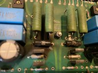
Those look like vitreous enamel wire wounds to me.
The blown ones are in black. I think the green one are vitreous enamel or Sfernice.
I cut one of them out and did not find any wire winding. Instead it has a white ceramic core covered in some grey color material. Therefore my guess is that they are metal oxide resitors but still unsure.
The length is about 14mm and therefore I think it’s about 2w-3w, isn’t it?
It was the black ones I was looking at 🙂 and yes, they look about 3 watt. I said wirewound because it looked as if there might be a spiral of something under the cracked off coating... working from pictures is not always easy though.
I can't see them being very critical and a metal oxide type would be non inductive if you got some of those.
I can't see them being very critical and a metal oxide type would be non inductive if you got some of those.
Thanks, Mooly. You are right. I have checked the resistor used in the same position in the previous version which is the YBA integre alpha DT. The Alpha has the usual green SETA vitreous wire wound resistors in that place. This one is easy to find.
